11
\$\begingroup\$

I want to design a CC/CV (constant current/constant voltage) circuit in which I can set the voltage limit or current limit with DAC's 0 to 5V range. I know how to design variable CC circuits and CV:
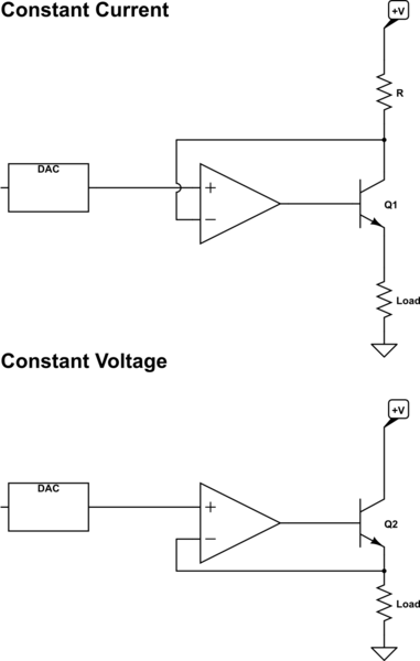
schematic

simulate this circuit – Schematic created using CircuitLab

Here is my problem, I need to design a fairly accurate programmable constant voltage and constant current circuit (the output needs to be 0.1% and within 100uV of the DAC input) the constant current portion also needs a similar accuracy and to be able to source 200mA at 0V to 7V.

I also have temperature req's and noise req so I'll be building this with low tempco opamps low noise op amps. I'm not so worried about that now. Right now I'm trying to find a good circuit topology, which in all the literature that I have this type of circuit is not covered. I don't want to use a DC to DC because of the ripple.

What is a circuit topology that I can use to build a precision CC/CV circuit?

(I could also use a precision LDO if needed) Bonus points if it can source and sink current, I can build the rails around the circuit.

\$\endgroup\$
5
  • \$\begingroup\$ Interesting question. Even assuming temp-stabilized, I'm still stuck on the difficulty of accurate and 0.1%. How exactly will this be calibrated to NIST traceable standards and then maintained against drift over time? Precision is one thing. Accuracy yet another. \$\endgroup\$
    – jonk
    Commented Apr 12, 2017 at 19:32
  • \$\begingroup\$ @jonk I don't know if this needs to be nist tracable, but I need to think about that, Thanks \$\endgroup\$
    – Voltage Spike
    Commented Apr 12, 2017 at 21:54
  • \$\begingroup\$ @laptop2d I've specialized in temperature measurement. People want accuracy as well as precision as well as repeatability between instruments. You get nothing but pain from customers if they buy 5 instruments and measure the same freeze point with all 5 and get different values. Whether or not they are willing to pay for that, is another matter. But it's what they want. Had to maintain NIST traceable standards, usually only one step away (we didn't hire NIST, but hired someone who did.) \$\endgroup\$
    – jonk
    Commented Apr 12, 2017 at 22:08
  • \$\begingroup\$ @laptop2d For temperature, you pay for a few exact calibration points (say 5 or 6) and in between you have to figure out the worst case deviations in order to provide specifications to the customer. If you support a wide-range of currents, you will have your own non-linearity issues to figure out, as well. This 0.1% thing is achievable. So is 0.01%. But I have to tell you that those 0.1% pieces of equipment were expensive and the 0.01% pieces were nearly sky-high (at the time, 20 years ago.) I used them, too, because we needed precision current to operate electron beams for IC wafer masks. \$\endgroup\$
    – jonk
    Commented Apr 12, 2017 at 22:15
  • \$\begingroup\$ Usually my requirements are in the uV or nV range so I don't think a set point accuracy in the 10uV range will be a problem. We'll probably calibrate the circuit. A 10 Ohm 0.01% resistor is expensive but it can save you a lot on calibration and give you accuracy. \$\endgroup\$
    – Voltage Spike
    Commented Apr 12, 2017 at 22:26

4 Answers 4

10
\$\begingroup\$

If you want precision, then your CC source doesn't cut it, what with transistor alpha an' all.

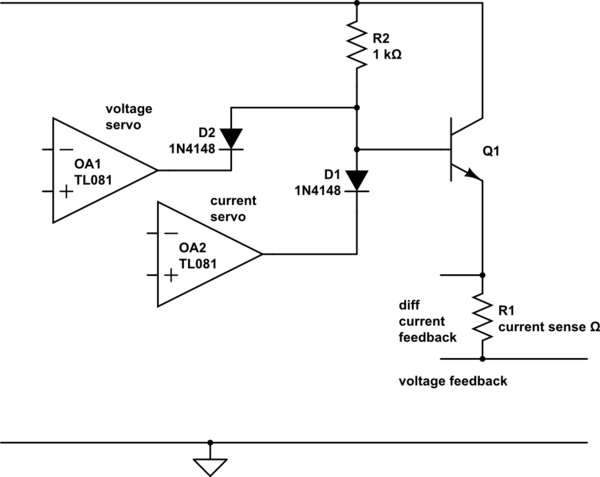
The classic way to do this is with two loops

schematic

simulate this circuit – Schematic created using CircuitLab

Both the voltage and the current feedback are scaled and referred to ground, and compared against your DACs, and the comparisons OR'd into the output control, suggest a darlington for convenience. Whichever loop is 'over' pulls down the collector and regulates the output.

Note that stability needs to be maintained, ie designed for, so the comparison is done with lowish gain. If high gain is needed for precision, add an integrator in the loop. I would guess that such would have to come after the control OR, otherwise the inactive integrator would saturate and take a long time to recover when needed to take over.

With your low voltage and current requirement, a linear supply is all that's needed.

\$\endgroup\$
5
  • \$\begingroup\$ I realize I could substitute an LDO or mosfet in for the BJT but that will change some aspects of the design. If your using a BJT for the current source won't the op amp compensate for whatever the BJT is doing? \$\endgroup\$
    – Voltage Spike
    Commented Apr 12, 2017 at 16:22
  • \$\begingroup\$ are you referring to my circuit, or your circuit, I don't understand the question? \$\endgroup\$
    – Neil_UK
    Commented Apr 12, 2017 at 16:30
  • \$\begingroup\$ I was referring to this: "If you want precision, then your CC source doesn't cut it, what with transistor alpha an' all." \$\endgroup\$
    – Voltage Spike
    Commented Apr 12, 2017 at 16:53
  • 2
    \$\begingroup\$ @laptop2d I'm pretty sure that he means that the base current of the BJT in the constant current supply you proposed skips the current sensing resistor. An extra current will flow from the opamp to the load, inversely proportional in magnitude to the transistor amplification factor (alpha), and the opamp has no way of compensating for it. \$\endgroup\$
    – jms
    Commented Apr 12, 2017 at 17:22
  • \$\begingroup\$ I see it now, thanks for that. I suppose you could put the current sense after the BJT and do differential current sensing like this post suggests \$\endgroup\$
    – Voltage Spike
    Commented Apr 12, 2017 at 17:33
3
\$\begingroup\$

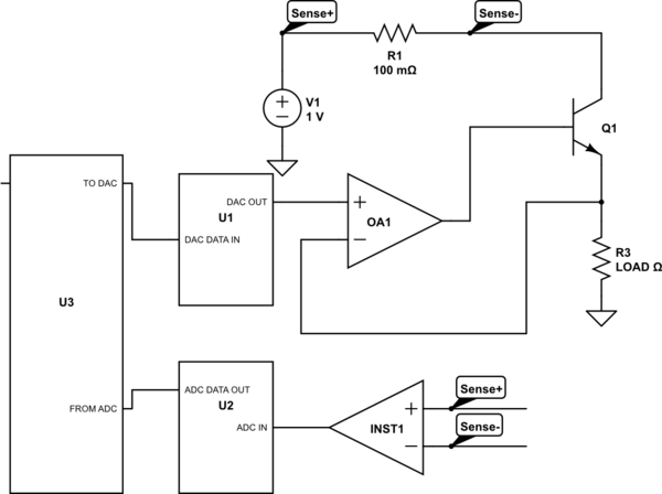
OK, so what i suggest is actually two loops: current loop over voltage loop. That means, you have a current command (which will be a limit), then a voltage command. The output to the DAC is max(voltage command/current loop output). So as long as the current limit is not reached, current loop is saturated and doesn't interfere. The only thing you have to do is to measure the voltage and the current, which is pretty basic stuff.

As per circuit- well, you didn't say a word about voltage/current requirements. So maybe actually simplest way is an emitter follower for power amplification of the DAC and a very small current sense resistor for the current measurement.

Depending on your application and available digital components, i may suggest sigma-delta ADCs to measure the current. Some have very nice, very accurate built in PGA, so you will be able to tune the system very nicely.

So schematic is below. U3 is your microcontroller. In a sense the whole system is similar to one from the other answer, but the current loop should be easier tunable, but will have lower bandwidth.

Sorry, the INST- instrumental amp; also forgot a resistor on base, but you get it.

schematic

simulate this circuit – Schematic created using CircuitLab

Several more words about system behavior. If everything is done correctly, current loop will start from zero and will ramp up the voltage slowly up to voltage command. But if system is normally working in CC mode, there are some special cases. If load is suddenly disconnected, then reconnected, for some time it may be under current higher than the limit. So it may be important to detect disconnected load and reset the current PID loopm

\$\endgroup\$
9
  • \$\begingroup\$ I kind of did say a few things about voltage and current requirements. Do you think you could draw an example circuit with the tool? \$\endgroup\$
    – Voltage Spike
    Commented Apr 12, 2017 at 16:21
  • \$\begingroup\$ Yes, i missed the numbers. OK, working on the circuit. \$\endgroup\$
    – user76844
    Commented Apr 12, 2017 at 16:22
  • \$\begingroup\$ Done! 123456789 \$\endgroup\$
    – user76844
    Commented Apr 12, 2017 at 16:47
  • \$\begingroup\$ Laptop, do you know how to arrange current loop in the microcontroller? \$\endgroup\$
    – user76844
    Commented Apr 12, 2017 at 17:20
  • \$\begingroup\$ Yeah, one problem is the software engineers that I work with are not good with real time stuff so I don't know if I would want to use 'firmware in the loop' \$\endgroup\$
    – Voltage Spike
    Commented Apr 12, 2017 at 17:27
2
\$\begingroup\$

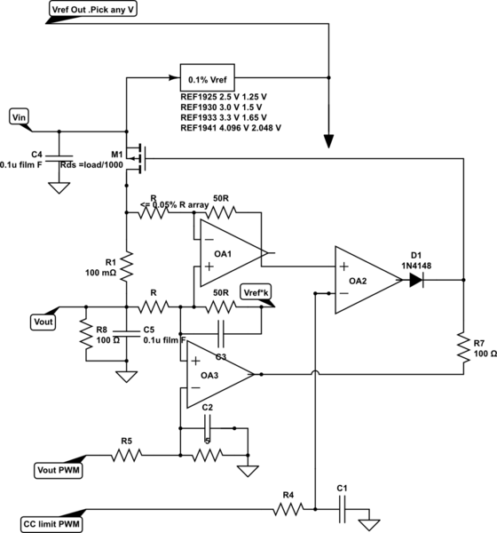
- depending on system specs, otherwise I would NOT use DAC but rather 10 bit PWM (1024)

- I would choose <=0.1% Vref and choose linear high side CC and CV

schematic

CC loop inverted by hasty schematic (sorry)

choose k=0 to 1 for CC= x to max

\$\endgroup\$
12
  • \$\begingroup\$ Tony, could you please explain the circuit? \$\endgroup\$
    – user76844
    Commented Apr 12, 2017 at 17:21
  • \$\begingroup\$ It's a classic LDO design read any datasheets. OA1 is Isense amp from 100mV drop and OA3 is Vreg while OA2 is Imax reg. with down control only. The key is dont use an expensive DAC or less accurate one. \$\endgroup\$
    – D.A.S.
    Commented Apr 12, 2017 at 17:22
  • \$\begingroup\$ Damn you are smart! Did you draw all this by yourself and no schematics?? \$\endgroup\$
    – lucenzo97
    Commented Apr 12, 2017 at 17:24
  • \$\begingroup\$ after 40 yrs I can do this in my head.. just now here \$\endgroup\$
    – D.A.S.
    Commented Apr 12, 2017 at 17:25
  • \$\begingroup\$ So why would you draw it? \$\endgroup\$
    – user76844
    Commented Apr 12, 2017 at 17:25
1
\$\begingroup\$

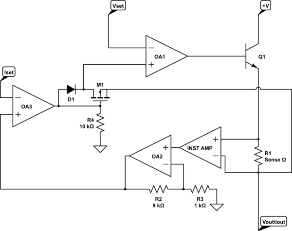
After doing much more searching I found one more circuit from eevblog that I thought I'd like to add to the list because it's interesting. Instead of using diodes in a 'max' like configuration, it uses a mosfet and a diode to switch from CV to CC.

schematic

simulate this circuit – Schematic created using CircuitLab

\$\endgroup\$
6
  • \$\begingroup\$ curiously almost identical to mine with diode crossover and IA config, but I have doubts with 0.1% accuracy \$\endgroup\$
    – D.A.S.
    Commented Apr 12, 2017 at 18:46
  • \$\begingroup\$ Not quite, yours doesn't use a mosfet and a diode to select between voltages it uses an op amp which would have an offset. This one would give you a more direct feedback path with no offsets for voltage feedback when your not in CC mode. Plus this one uses a BJT not a mosfet for the main current limiter. \$\endgroup\$
    – Voltage Spike
    Commented Apr 12, 2017 at 18:50
  • \$\begingroup\$ yes it has an extra Q (FET ) instead of diode with high gain causing potential stability issues, \$\endgroup\$
    – D.A.S.
    Commented Apr 12, 2017 at 18:54
  • \$\begingroup\$ I thought I'd throw it on to the list \$\endgroup\$
    – Voltage Spike
    Commented Apr 12, 2017 at 18:56
  • 1
    \$\begingroup\$ There are at least two errors in the schematic: OA1 is inverted (voltage and current feedback should be negative), and M1 should be a P-channel enhancement mode part (it should conduct when the output of OA3 is low, and it should block when it is high). Currently M1 is a N-channel enhancement mode MOSFET. \$\endgroup\$
    – jms
    Commented Apr 14, 2017 at 17:37

Your Answer

By clicking “Post Your Answer”, you agree to our terms of service and acknowledge you have read our privacy policy.

Not the answer you're looking for? Browse other questions tagged or ask your own question.