0
\$\begingroup\$

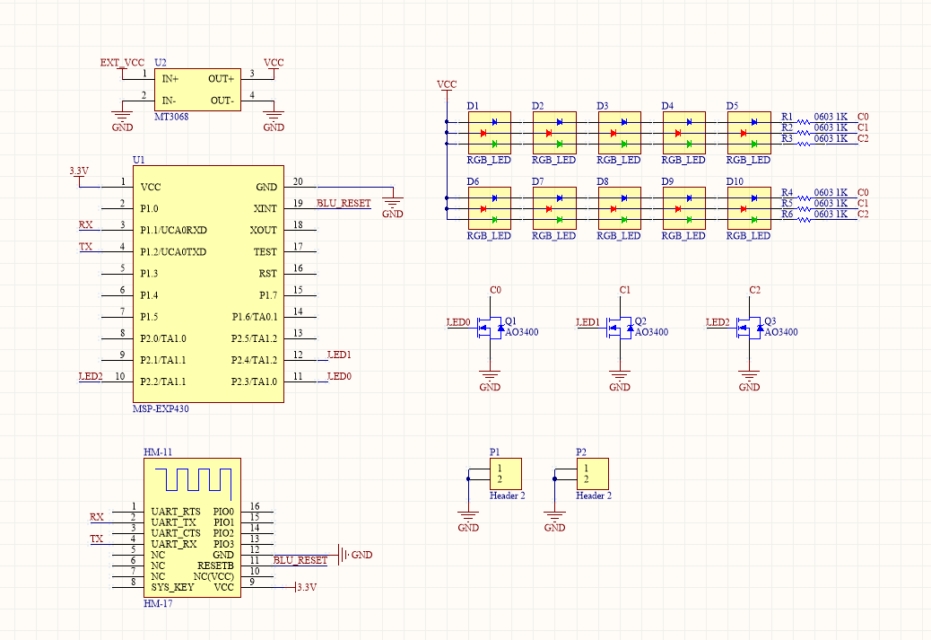
I am trying to make a msp430 controlled Bluetooth RGB lamp. The program works perfectly right now. But the problem is: when running for a while or as soon as I connect the led driver power supply (I soldered many boards to troubleshoot the problem. But I failed), some led begin to blinking (the unstable kind.) and it's like the color is abnormal. For example, if I only turn on Q1, then the blue should be the only color, but actually, some led will also light up red color, and some even show red only. I don't know what cause this problem.

I one board I soldered, I try to lower the MT3068 voltage to around 14V (15V originally). This time, the stable working time lasted longer (not broken as soon as possible). But eventually, the cross-light-up still occurs.

How should I work around this.

enter image description here

\$\endgroup\$
6
  • \$\begingroup\$ Did you connect the grounds of the power-supplies together properly? \$\endgroup\$
    – Transistor
    Commented Sep 30, 2017 at 8:34
  • \$\begingroup\$ Yep. This is actually an msp430 launchpad extender board. I connect the GND as the schematic shows. MT3068 module has the same ground as the msp430 lauunchpad. \$\endgroup\$
    – Burning
    Commented Sep 30, 2017 at 9:00
  • \$\begingroup\$ What's the current rating of your power supply? Also, do you have a datasheet for the MT3068? I couldn't find any info on it online. \$\endgroup\$
    – Polynomial
    Commented Sep 30, 2017 at 10:37
  • \$\begingroup\$ Current rating should be enough. Sorry, it should be 3608. Here is the datasheet olimex.com/Products/Breadboarding/BB-PWR-3608/resources/… \$\endgroup\$
    – Burning
    Commented Sep 30, 2017 at 18:18
  • \$\begingroup\$ looks like you want to pull out the logic analyzer and see what those LED0, LED1, and LED2 pins are looking like after the circuit bugs. \$\endgroup\$
    – hedgepig
    Commented Oct 1, 2017 at 12:07

1 Answer 1

1
\$\begingroup\$

Did you check the output of the MT3608? Where is the inductor, diode, and feedback sense resistors?

What is the voltage of EXT_VCC?

Five red LEDs will need about 12V.
Five blue or green LEDs in series will need about 15V.
VCC must be more than the forward voltage of the five blue and green LEDs. 15V may not be enough. The resistors for the blue and green should be more like 25 ohm. 1K is much too much. 1K on the red will give you about 5mA, probably insufficient.

What is the part number for the RGB LED?

Apply ground to signal C1. Do the red LEDs illuminate?
Apply ground to signal C0. Do the blue LEDs illuminate?


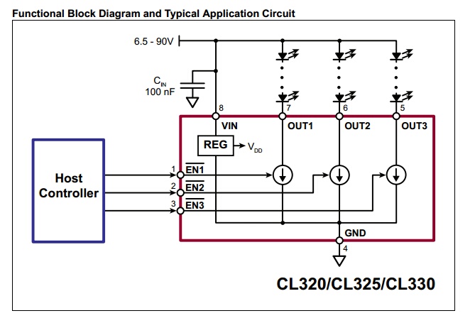
You could get rid of R1-R6 and Q1-Q2 by using a triple output CCR like the Microchip CL320 (20mA per channel). This way resistor values will not matter and the interface to the micro is simplified.

Microchip CL320 LED Driver

\$\endgroup\$

Your Answer

By clicking “Post Your Answer”, you agree to our terms of service and acknowledge you have read our privacy policy.

Not the answer you're looking for? Browse other questions tagged or ask your own question.