4
\$\begingroup\$

Is there a device to only allow AC power to "flow" one-way?

Scenario: I have a circuit in which I would like to draw AC power from two sources: One source is good ole wall (grid) power and the other source is a tie-in inverter. The problem is is that if the tie-in inverter ever exceeds the power needs of the circuit, the excess power will "leak" out and be available throughout my house. I need to prevent this.

I cannot simply throw a couple relays between my circuit and the wall and only switch them on when the draw of the circuit exceeds the capability of the tie-in inverter because the tie-in inverter won't do squat by itself--it can only feed into an existing AC system.

Is something like a DIAC what I need? I read a little about it, but was confused as to how that would actually fit my needs. Is there a device that prevents AC power from escaping a circuit, but allows it to flow in? What if I take grid power from a UPS, would that prevent "back flow"? If not, what must I create to be functionally equivalent?

edit: Motivation:

The reason I want something like this is because after talking with the power company, it is very expensive to perform an interconnect with the grid and would be super pointless in an apartment. If you want to provide any power locally (solar, wind, etc) you have to interconnect so the grid doesn't explode with (rare) excess power. Now of course, this isn't much of an issue if it were just me occasionally spewing out extra power, but I understand how serious the issue becomes if lots of people did it (without interconnect), so I do want to play by the rules.

I was informed that even with an itsy bitsy tie-in inverter (we're talking ~30Watts), my power company would eventually find me out and I'd be forced to stop or pay for an interconnect installation. I'm still not entirely sure how they would find out since our fridge, for example, is plugged in all the time and draws way more than 30 Watts, but they said eventually power will leak out and they'd see it.

So my end game is a single powerstrip that draws from my own generated power (granted a very small amount) supplemented by the grid in a safe way that will not ever leak out in the obscure event that my load is less than my locally produced power.

\$\endgroup\$
10
  • 7
    \$\begingroup\$ You show no understanding of electricity and are proposing modifying a mains system. Walk away now and hire a qualified electrician before someone gets hurt. \$\endgroup\$
    – RoyC
    Commented Nov 30, 2017 at 16:08
  • 3
    \$\begingroup\$ @RoyC: I deleted your second comment because it was dangerous and misleading.You clearly have no understanding of how a grid-tied inverter works. It simply converts the available input power to grid power -- it can't distinguish one grid load from another. \$\endgroup\$
    – Dave Tweed
    Commented Nov 30, 2017 at 16:41
  • \$\begingroup\$ @Dave Tweed I have a very good understanding of how a Grid Tie inverter works although I put things in a deliberately simplistic manner . How exactly was my statement misleading?. The inverter will create a voltage waveform at or slightly higher than the line in. If the local load is not enough to soak up that power it is fed back to the grid it does not leak out into the OPs house or put simply the inverter deals with the excess power. \$\endgroup\$
    – RoyC
    Commented Nov 30, 2017 at 17:06
  • 3
    \$\begingroup\$ @RoyC: As I said, the inverter cannot distinguish loads inside the house from loads outside the house (the rest of the "grid"). You are still oversimplifying. \$\endgroup\$
    – Dave Tweed
    Commented Nov 30, 2017 at 17:20
  • 2
    \$\begingroup\$ One of the reasons for safety approved grid-tie not discussed in your question is that you must prevent backfeeds during a power cut. If you don't you run the risk of electrocuting a lineman out on repair. Even if you only have a low powered source the shock could indirectly cause a fatality if, for example, s/he fell from a ladder as a result. \$\endgroup\$
    – Transistor
    Commented Aug 27, 2020 at 19:35

7 Answers 7

4
\$\begingroup\$

Here are some thoughts.

As Pieter said in his answer, this would be easy for DC: you would use a diode to prevent current to flow back to the grid.

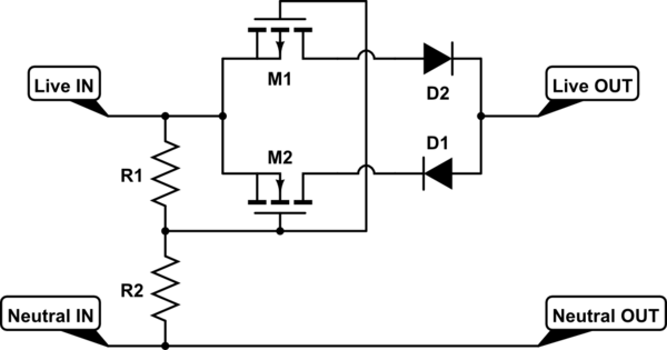
But for AC, you can design something that behaves like the diode in DC:

schematic

simulate this circuit – Schematic created using CircuitLab

You would connect your inverter and your home equipment to the “OUT” side.

But I would not recommend this anyway, since you don’t know how your inverter will behave if the equipment does not drain all the power the inverter tries to push…

\$\endgroup\$
3
  • \$\begingroup\$ One could even have problems with this circuit if there are reactive loads in the network. \$\endgroup\$
    – Vovanium
    Commented Jan 31, 2019 at 13:57
  • \$\begingroup\$ @Vovanium Good point, one more reason not to recommend it. \$\endgroup\$ Commented Jan 31, 2019 at 14:36
  • \$\begingroup\$ @Vovanium: The problem with such a circuit when using reactive loads is that it would work too well: most reactive expect to draw energy during part of each cycle, send a lot of it back during some other part, and then repeat the process. This circuit would prevent the "send energy back" part of that sequence. \$\endgroup\$
    – supercat
    Commented Jul 26, 2021 at 17:46
3
\$\begingroup\$

Disclaimer: I am just an amateur, get professional advice.

If you have two DC sources it would be easy, you just add a one way (diode) and power/current can only flow in one direction.

You might be able to simulate this by feeding grid into UPS(double conversion AC->DC->AC) and then having your grid-tied inverter connected to the output of the UPS.

Thus if you draw low power from the UPS output the grid-tied inverter will elevate the voltage slightly but nothing will flow back through the UPS AC->DC

It might also provide the additional benefit of extending the runtime of the ups, and allow the grid-tied inverter to operate when the mains power fails.

By connecting the grid-tied inverter to the output of a double conversion UPS you have effectively removed it from the grid, and created your own isolated grid.

\$\endgroup\$
1
\$\begingroup\$

You got the wrong kind of inverter. A grid-tied inverter is never used for one specific load; you use it to convert the available power to grid power to supplement anything that might be connected to the grid.

If you want to supply power to a specific load only, you need the other type of inverter, which simply converts DC to AC with no tie to the grid at all.

\$\endgroup\$
4
  • \$\begingroup\$ Well the thing is, 90% of the time the inverter will not meet the load requirements of the circuit and I'd like to supplement from the grid. What if I take grid power from a UPS? Would that prevent leaking back out to the rest of a house/grid?d \$\endgroup\$
    – Paul
    Commented Nov 30, 2017 at 19:06
  • \$\begingroup\$ So why is it important that when the inverter output exceeds the load requirements, you don't allow power to flow to the rest of the house? You can't have it both ways. \$\endgroup\$
    – Dave Tweed
    Commented Nov 30, 2017 at 19:08
  • \$\begingroup\$ Hey Dave, thanks for the comments. I've updated the question to reflect why I want this. Thanks! \$\endgroup\$
    – Paul
    Commented Nov 30, 2017 at 19:32
  • \$\begingroup\$ I find it hard to believe that even a small apartment would ever use less than 30W, so the only thing that the power company would ever notice is that your average net power consumption drops by 30W, which for all practical purposes is undetectable. You would never actually deliver power to the grid. If there's a power outage, your grid-tied inverter will also shut down. \$\endgroup\$
    – Dave Tweed
    Commented Nov 30, 2017 at 22:26
1
\$\begingroup\$

It's going to be almost impossible without a deep knowledge of how that particular inverter detects the incoming mains supply. Block the mains, and the inverter will shut down, as it's designed to do. Leave the mains connected, and it will start exporting, as it's designed to do.

It's not clear why you'd want to do this anyway.

\$\endgroup\$
1
  • \$\begingroup\$ Hey Simon, thanks for the answer. I updated my question to include why I would want to do something like this. Thanks! \$\endgroup\$
    – Paul
    Commented Nov 30, 2017 at 19:31
1
\$\begingroup\$

Here is my idea. Use a double conversion topology. It is the same approach used by premium UPS systems to isolate the load from the lines, except with multiple inputs.

For each line input, you would need an AC/DC converter. It should be programmable so you can limit the input current to the max that the line supports. On the DC side, you would need to decide on a DC bus voltage. This decision would be based on your budget/capacity. I would recommend a minimum of 48V since there is a lot of gear choices that work at that voltage cheaply. Higher DC bus voltage will allow higher capacity, efficiency with smaller conductors, but above 100V the gear can be expensive.

For the DC bus, you can optionally add a bank of batteries. This will provide buffering during transient loads and some backup capacity depending on your budget. If you are not running off grid lead acid should be fine since the cheaper AC/DC converters can be programmed to handle the charge profile of those batteries. A Li-Ion bank would be better performance, but then you have the added expense of a battery management gear (or your house goes poof).

Now you add a single DC/AC inverter to carry your loads. You can even add more inverters for redundancy/capacity and have them synched.

This design is scalable to handle as many AC inputs as you want, just add one AC/DC converter for each. You can even add a DC input from solar/wind etc. with a controller for those sources tuned to your DC bus voltage.

This might be overkill, but I believe most of this gear can be sourced cheaply and the flexibility is worth the effort.

Sorry for not drawing a diagram, but I suck at that. Maybe someone else here can illustrate this approach or chime in.

\$\endgroup\$
1
\$\begingroup\$

Wrong kind of inverter. Get rid of it.

Take a close look at your solar panels. THEY ARE ALREADY DC. So just use actual diodes.

 Solar panel --------- Diode ----\
                                  > ---- Inverter ---- Load
 DC power supply ----- Diode ----/

That was easy

The inverter is a "standalone" inverter like you'd use in your van to power a fridge. It is NOT a grid-tie inverter. The grid-tie inverter you have now is a distraction and a waste of time, onto Craiglist it goes.

I'm assuming all common consumer-grade stuff found at truck stops: typically "12V" solar panels, common 12V DC power supplies, and a consumer-grade 12V-input inverter like Best Buy sells, that'll have a couple of 120V sockets on it. The diodes might be a special order. You could substitute 24V if you have some distance to travel and want to reduce voltage drop.

For bonus points...

Replace the "Solar Panel" with "Solar panel + DC charge controller calibrated to charge a lead-acid battery". You can use MPPT if you feel like paying for it. Also, use a common 12V DC power supply (or 24V if your solar system is 24V nominal). This will mean the solar power supply has something of an "edge" on DC power sourced from utility, and will encourage maximum solar use before blending in utility-sourced DC.

The important concepts here.

First and foremost, you must not connect an AC source to the grid. As you have noticed, making AC unidirectional is hard. That means if your inverter is running while grid power is down, it WILL backfeed the grid and energize power lines feeding your house, even backfeeding through transformers to create 2400V or 12,000V voltages on the distribution lines. You may not believe a paltry 30 watt solar can do that, but yeah. It can. If a lineman gets nailed by that, dead lineman. How do grid-tie solar installations do it? They follow a standard for syncing and following the grid called UL 1741, which causes them to drop out when the grid goes down. This is not a thing you want to get into.

Your existing inverter is UL 1741, hence its unfitness.

Second, AC mains power is not to be trifled with. You must not do anything with it in a way that doesn't conform with Electrical Codes and the UL White Book. Which is all about construciton methods and enclosures. The setup I outline here puts the entire system in the low-voltage zone, which is a much safer place to do that kind of thing.

I'm still not entirely sure how they would find out since our fridge, for example, is plugged in all the time and draws way more than 30 Watts

Fridges pull about 100-150 watts when running and about 42 watts on average. A 33% duty cycle implies very close to 0 watts when not running.

Is there a device that prevents AC power from escaping a circuit, but allows it to flow in?

No, there isn't. If there was, "generator transfer switches" would be a lot simpler than they are. So there's about a billion dollars of market demand searching for that, and they haven't found it. It doesn't exist. Since it's easy for you to work in the DC regime (and vastly safer), work there.

Two-way flow of AC is so ubiquitous that when you hook up a generator, you just stick a breaker in the panel and backfeed it - with a mechanical interlock that effectively creates a DPDT switch so both generator and utility can't be on at once. Solar panels also just backfeed a breaker, relying on UL 1741 to not kill linemen.

I want to use that inverter, though

Trying to make a UL 1741 inverter do what you want is akin to modifying a car so it drives on water. Dog simple idea, but so toe-curlingly difficult to implement that it is a non-starter.

\$\endgroup\$
0
\$\begingroup\$

Re Paul Roger's idea, there seems to be two key concerns worth exploring:

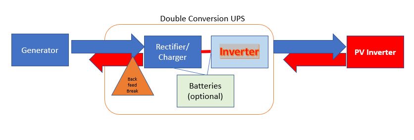
enter image description here

Since the double conversion UPS will be fed any excess current generated from the PV inverter,

a) The UPS inverter must have current handling capacity equal to or greater than that of the PV inverter otherwise it can trip, overheat or even fry depending on circuitry. e.g. My PV array and inverter can put out 7KVA but my UPS is only 3KVA.

b) the UPS must be able to deal with this backfeed into its inverter. UL 1778 Section 29 deals with backfeed during battery operation only by breaking line and neutral; this means the current will flowback also into the Generator if the Generator is on.

\$\endgroup\$

Your Answer

By clicking “Post Your Answer”, you agree to our terms of service and acknowledge you have read our privacy policy.

Not the answer you're looking for? Browse other questions tagged or ask your own question.