1
\$\begingroup\$

I have installed a "Sun Series Grid Tie Power Inverter" on our house. I have half the panels connected so far, it is working great. But before I connect the rest of the panels I need to get the limiting function of the inverter working. This inverter will measure the the demand of the home and make sure that excess power is not driven back into the grid. They provide one CT transformer, it is only meant to work on one side of U.S. mains. These inverters auto detect and can be hooked to 240, mine is to reduce line looses between the inverter and the mains. So, in Europe where most resident mains are just a single 230V drop, they work fine.

So the shipped CT is 100A/50ma. That comes out to 400:5, the same as a CT400A, I got a couple of CT400A clamp-ons that will fit my mains. Also, I will hook the shipped CT up with a known load and confirm that the burden resistance of the inverter CT input is 50 ohms. (Though, that seems kind of high.)

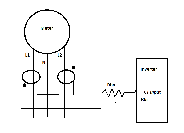
So just to be sure my thinking is right if I wire like this:

enter image description here

Where Rbo == Rbi.

(Sorry for the goofy looking schematic, I hope it is clear.)

I should be able to limit my total demand just fine. It looks like there is a guy selling just this with cheap CTs for up to $200 on EBay.

Update:

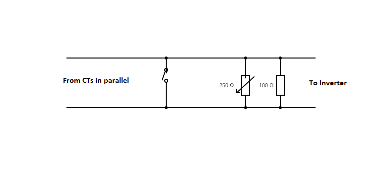
Thanks to Andy aka, the lights came on. So I put the CTs in parallel and it works! The watts on my service meter and the inverter match up. As this is about current, Rbo needs to be a shunt. And it turns out the burden resistor in the inverter is ~50 ohms. I did the circuit like this. enter image description here
\$\endgroup\$

2 Answers 2

4
\$\begingroup\$

A CT output bears a strong resemblance to a current source so, putting current sources in series is going to be problematic. Why not put the CT outputs in parallel like you would with current sources. I'm assuming that the burden resistor is going to be used.

So the shipped CT is 100A/50ma. That comes out to 400:5

No, that comes out at a turns ratio of 1:2000.

\$\endgroup\$
1
  • 1
    \$\begingroup\$ Current source, well slap my head. Thinking about it, there is no good reason I can't put the CTs in parallel. And they are the same. They spec these things like that and 400 x 5 = 2000. I'll update my question instead of a solution as you brought it home. \$\endgroup\$
    – lakeweb
    Commented Jul 22, 2021 at 14:54
0
\$\begingroup\$

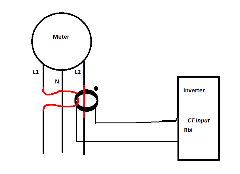
you have a 100A/50mA transformer that's 2000:1

get a 4000:1 trandsromer and put both line wires through it one forwards and one backwards.

that way you'll measure both halves of your supply at half ampliutude.enter image description here

\$\endgroup\$
2
  • \$\begingroup\$ Thanks, I know that would work. But this is a 200A breaker box with 3/4" formed cables for the mains. There is no way to rearrange the mains much less deal with a CT that large. This has to be a two CT solution. \$\endgroup\$
    – lakeweb
    Commented Jul 22, 2021 at 15:03
  • \$\begingroup\$ @PeteW It'll work as drawn - L1 is passing through the CT back to front and L2 front to back. \$\endgroup\$
    – jms
    Commented Jul 22, 2021 at 19:15

Your Answer

By clicking “Post Your Answer”, you agree to our terms of service and acknowledge you have read our privacy policy.

Not the answer you're looking for? Browse other questions tagged or ask your own question.