0
\$\begingroup\$

I have this card to control my pool heatpump.

This card allow the display of several information:

  • input temperature
  • output temperature

and allow at least one command:

  • heat the water.

What I do not understand is how this system communicate with the heatpump as I only see three wire.

I would like to gather and command this heatpump from another device.

Any idea how I could, based on the picture, determinate or at least shortlist the protocol used to communicate with the heatpump ?

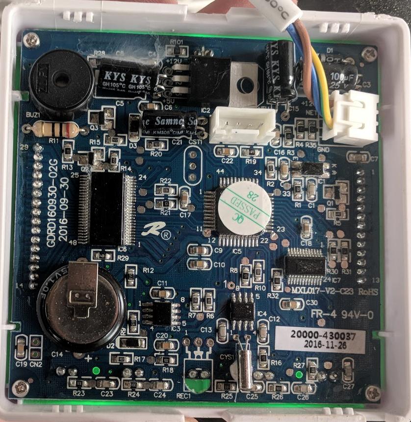
Unknown communication system

\$\endgroup\$
9
  • 3
    \$\begingroup\$ Hook up your scope and have a look \$\endgroup\$
    – PlasmaHH
    Commented May 25, 2018 at 20:45
  • 1
    \$\begingroup\$ These three wires are, based on their color and the kind of cable used, almost certainly the power lines + protective ground. So, communication likely doesn't happen using these at all. Does either of your devices happen to have some FCC id or other indication it does wirelss communication? also, what is the unused 4-pin connector in white used for? \$\endgroup\$ Commented May 25, 2018 at 20:55
  • 1
    \$\begingroup\$ "What I do not understand is how this system communicate with the heatpump as I only see three wire." - three wires is pretty much anyone needs to communicate between things electronically. \$\endgroup\$
    – Andy aka
    Commented May 25, 2018 at 21:16
  • 1
    \$\begingroup\$ @Andyaka as wireless comms engineer, I'd argue it's three superfluous wires ;) but seriously, these definitely look like they are primarily used to transport power, and I don't see any of the transformer-type devices that you'd normally see when looking at systems that superimpose a higher-frequency signal onto a power line. \$\endgroup\$ Commented May 25, 2018 at 22:24
  • 2
    \$\begingroup\$ It's hard to tell from the angle, but it looks like the tan(beige?) wire is +12V, blue is "NET" (network?), and yellow/green is GND, based on the silkscreen... if true, looking at the blue wire on a scope may help. \$\endgroup\$ Commented May 25, 2018 at 23:02

1 Answer 1

1
\$\begingroup\$

with only three wires and two of those labeled to be carrying power, the signaling will be some type of asynchrounous serial.

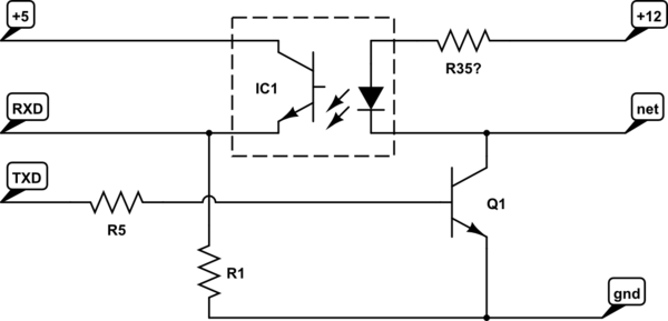
further guessing IC1 looks like an optocoupler and Q1 seems to be connected too, so I'm guessing NET idles high, using a pull-up via the opto-coupler and signaling is done using Q1 as a pull-down something like this:

schematic

simulate this circuit – Schematic created using CircuitLab

\$\endgroup\$

Your Answer

By clicking “Post Your Answer”, you agree to our terms of service and acknowledge you have read our privacy policy.

Not the answer you're looking for? Browse other questions tagged or ask your own question.