1
\$\begingroup\$

I'm currently working on redesigning the control circuit of a CNC machine (more specific: an Isel milling cutter). Only the digital part will be of interest, I'll keep the old power electronics (motor drivers and power supplies). Currently all parts of the circuitry are working well independent of each other, but when it comes to putting it all together, my circuit fails at several spots.
Measurements told me that this is mainly due to enormous EMI, crosstalk and other forms of electric noise, radiated from the power supply and some high-frequency, high-current traces going to the stepper motors.

In the second version of the PCB I want to solve all these (and some other) problems by making the circuit design as resistant to interference as possible.
What worries me the most are some DC signal lines that share the same physical cable with the motor's power lines (4x 48V 3A 300kHz stepping speed - the actual current frequency will be by far lower) for 1-2 meters outside the control box (see picture below).circuit diagram
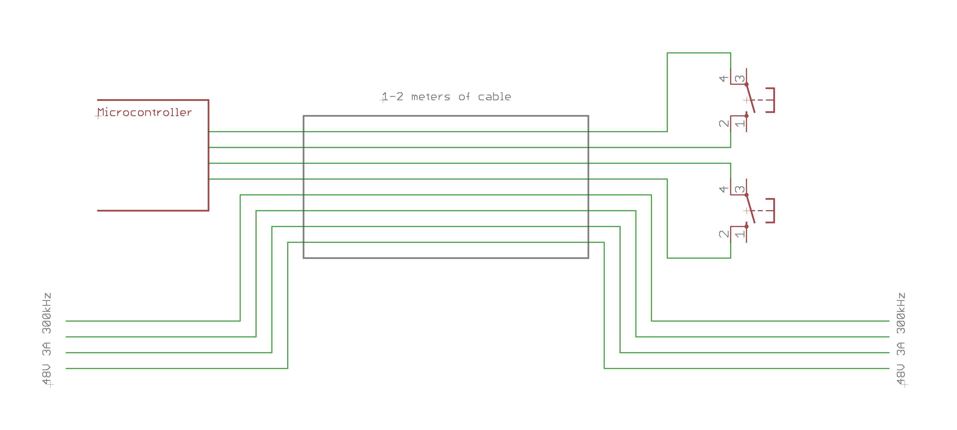
What is the best practice to connect switch to the microcontroller running at 3.3V? Simply connect one side of the swicth to Vcc and the other to a pulldown resistor? I fear that using a voltage as low as 3 volts will make it more likely that errors might occur: just 1V of interference induced into the wire will make it hard for the microcontroller to distinguish between LOW and HIGH. Should I apply a higher voltage, let's say 24V (that's the way the original datasheet states the switches should be used)? But in that case, how should the level conversion be done? A voltage divider would scale the error just as the signal, wouldn't it?

As you can see, I'm a little lost here, any help is appreciated. Thank you in advance!

\$\endgroup\$
7
  • \$\begingroup\$ Wiring these contacts on the 3.3V of the MCU is suicide. Don't do that. Do this \$\endgroup\$
    – Jeroen3
    Commented Oct 28, 2018 at 15:08
  • 1
    \$\begingroup\$ Your best bet is to study how PLCs do it and try to duplicate that kind of circuitry, if you don't want to use a PLC. Generally we're talking 12V or 24V, relatively substantial wetting current, and opto-isolators on each input. \$\endgroup\$ Commented Oct 28, 2018 at 15:28
  • \$\begingroup\$ Thank you for your comment, Jeroen3! Did I get you right: you suppose to use the 24V approach (as the post you linked states that one should not route/use cables over a long distance for weak signals) and connect the input via the divider/filter/schmitt-trigger circuit? \$\endgroup\$
    – K. Krull
    Commented Oct 28, 2018 at 15:29
  • \$\begingroup\$ Thanks for that hint as well, Spehro Pefhany. I'll do some research about PLCs and optocouplers/isolators \$\endgroup\$
    – K. Krull
    Commented Oct 28, 2018 at 15:30
  • 1
    \$\begingroup\$ If you wanted to be really robust, consider fiber-optic data transmission, completely immune to EMI. Many industrial processes use it for precisely this reason (ProfiBus, Sercos, etc.) \$\endgroup\$
    – rdtsc
    Commented Oct 28, 2018 at 16:02

2 Answers 2

1
\$\begingroup\$

This was bumped to top but I presume the problem has been long solved, one way or the other, still in general here are some thoughts of dealing with very noisy signals.

The very first thing that comes to mind is: Why are the signal and power wires running in the same cable? Is there any reason why you couldn't do that with a separate shielded cable? That cuts the near field coupling right out.

If that doesn't work or is not allowed for some reason, you can add common mode chokes to the control lines. That's explicitly designed to take out noise that's coupled to both wires as in your case.

Beyond that, you need some kind of capacitor with a button to suppress the button bounce and you could make that a simple RC low pass filter while you're at it. That can be arbitrarily low frequency althought going to megaohms is probably not a good idea. (100nF * 1meg = 100ms time constant or 1.6Hz corner frequency. Likely that'd stop the button working properly since you'd have to keep it pressed for a good while but 100nF + 100k would have 5x time constant of 50ms that should be good enough.

\$\endgroup\$
1
  • \$\begingroup\$ Though it's quite some time ago, I really appreciate your answer. Actually, what I have done is a) use 24V across the switch, since then errors are less significant, b) use a current-controlled optocoupler to shift down to 3.3V logic levels and c) use a RC filter just as you described. Maybe you could add that to your answer to make it easier to find that info for others. Anyway, in my opinion this is close enough to what actually solved the problem to mark it as accepted answer. BTW: Seperate calbes are not available since that part of the machine was not designed by me and is a given :( \$\endgroup\$
    – K. Krull
    Commented Jul 17, 2019 at 21:08
0
\$\begingroup\$

Lets compute the intensity of interference between some motor-driver cables and your new wires. Magnetic interference.

Assume those 300Hz (I doubt you meant 300,000 pulses per second) 3A pulses have 0.3uS edges. In the absence of ANY RINGING, the dI/dT will be 3A/0.3uS == 10Million Amps per Second.

Assume geometry of a single 3A cable packed against a sensor/return wiring pair, for 2 meters. Assume 2mm between the 3A cable and the other 2 wires; assume the other 2 wires also have spacing of 2mm (this makes the math easier to visualize).

Use the magnetically-induced-voltage formula, taken by combining the Biot-Savart Law with Faraday Law of Induction

Vinduce = [MUo*MUr * Area / (2*pi*Distance)] * dI/dT

With MUo = 4*pi*1e-7 Henry/meter, and MUr = 1 (air), the Vinduce becomes

Vinduce = [ 2e-7 * Area/Distance ] * dI/dT

Any idea how big this (interferer) will be? lets do the math

Vinduce = [2e-7 * 2meter * 2mm / 2mm ] * 1e+7

Vinduce = [2e-7 * 2] * 1e+7 = 4

Vinduce = FOUR VOLTS

\$\endgroup\$
3
  • \$\begingroup\$ Thanks for sharing these equations, I just guess the math doesn't help at this point, since I already measured the approximate interference. Furthermore, you were right about the frequency, 300kHz would be too much. I mixed up the step frequency and the motor driver's output frequency, which is by far lower due to microstepping. I'll edit the question accordingly. \$\endgroup\$
    – K. Krull
    Commented Oct 29, 2018 at 11:27
  • \$\begingroup\$ 10A/us isn't that fast btw... \$\endgroup\$
    – user16222
    Commented Oct 29, 2018 at 12:36
  • \$\begingroup\$ I used 10A/uS to bring integrity, using realistic numbers, to the answer I provided. No reason to be sensational. If the math showed only 7 milliVolts, twould be a different matter entirely. But FOUR VOLTS trashes any conventional logic system, even with hysteresis. \$\endgroup\$ Commented Oct 30, 2018 at 3:09

Your Answer

By clicking “Post Your Answer”, you agree to our terms of service and acknowledge you have read our privacy policy.

Not the answer you're looking for? Browse other questions tagged or ask your own question.