1
\$\begingroup\$

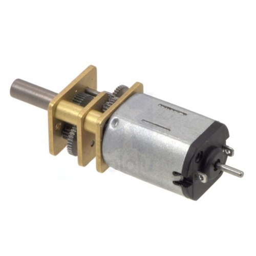
I'm trying to solder two noise filtering / decoupling capacitors to my small motors. One from each of the tags / motor terminals to the motors outside case. However it is just not working at all, the solder just is not soldering to the case. I don't want to heat the case up too long in case the heat damages the coils inside.

Is there any specific technique to solder to something like this large metal case?

Motor image

\$\endgroup\$
3
  • 1
    \$\begingroup\$ - Use Kapton tape. - Use wires instead of the capacitor leads as the solder-end termination. - Epoxy/glue. \$\endgroup\$ Commented Feb 21, 2014 at 22:03
  • \$\begingroup\$ Mount the motor frame wire between the motor and gear housing. Else solder to the brass. \$\endgroup\$ Commented Feb 21, 2014 at 22:25
  • \$\begingroup\$ A flux can help, in similar cases I use a cheap acidic liquid paste bought from a Chinese eshop (and a 50W soldering iron with a thick tip). \$\endgroup\$
    – alexan_e
    Commented Feb 21, 2014 at 22:38

2 Answers 2

3
\$\begingroup\$

I don't see the point in trying to solder to the case. If you want to add a suppressor cap, put it between the leads. You can then put another small cap on each lead to ground where it leaves the PCB.

You also don't know what metal the motor housing is made of. Some metals are hard to solder to even if you can apply enough heat. I doubt the housing is aluminum, but that is a good example. Aluminum oxidizes so fast in air that you never get a chance to solder to the aluminum. There is always a layer of aluminum oxide in the way. Other metals are difficult too for various reasons.

As a aside, if you have a old soldering iron or old tip that is otherwise no good anymore, you can use a lot of flux, make a big solder blob, and then scratch the aluminum under the blob with the soldering iron. The flux and solder blob won't let oxygen in there so the solder can actually wet the aluminum and make good contact. I have used this trick to solder to aluminum foil a few times.
\$\endgroup\$
3
  • 1
    \$\begingroup\$ I think the OP may be trying to do a two-filter capacitor arrangement as shown here: beam-wiki.org/wiki/Reducing_Motor_Noise - the motor case is used as a shield, but I don't know how necessary it is. \$\endgroup\$
    – JYelton
    Commented Feb 21, 2014 at 22:11
  • \$\begingroup\$ Thats right. pololu.com/docs/0J15/9, its the same here too \$\endgroup\$ Commented Feb 21, 2014 at 22:17
  • \$\begingroup\$ @bina: Those same docs also show just connecting a cap accross the terminals. I'd to that, then caps to ground on each line where it leaves the PCB. 100 nF could also be excessive, especially if you're trying to drive it with PWM. Some motors aren't meant to be soldered to, which is a hint that the motor wasn't meant for a two-capacitor noise suppressor. \$\endgroup\$ Commented Feb 21, 2014 at 23:00
0
\$\begingroup\$

To much heat might damage the magnets. It's called Curie Temperature and also applies to ferritas losing their permeability.

\$\endgroup\$

Your Answer

By clicking “Post Your Answer”, you agree to our terms of service and acknowledge you have read our privacy policy.

Not the answer you're looking for? Browse other questions tagged or ask your own question.