0
\$\begingroup\$

I'm using IR LEDs to blast away at a bunch of photodiodes, which I then latch into a shift-register and read into a PIC.

While reading/browsing about the topic I found an article that stated that the best way to ensure the conduction in the photodiodes would be to blast them with the LED radiation generated by a PWM signal at the center frequency of the modulated light sensor.

What I take from this is already what I intended to do, but the frequency aspects got me thinking.

Given that the PDs I'm using have an untraceable datasheet (I know that the reference is SWPD3330-16, from Sunwell), does anyone have any info that might help me figure out how to calculate the best frequency? As an alternative, is there any rule of thumb for this kind of problem? What would be a good starting point/estimate for the PWM frequency?

EDIT: After reading the comments, I would like to add the following:

  • I am using a photodiode. It looks like a LED and has two leads. The only thing I know about it is the aforementioned part number: SWPD3330-16.
  • The article does not specifically relate to my question, but on page 5 (2169), in the paragraph starting with "Step 2", you'll find what I quoted. LINK

EDIT2:

  • I found in a folder here at work the datasheet (in chinese) for this photodiode. It only covers mechanical aspects and (unfortunately) a few electrical specs (in parenthesis are the test conditions):
    • forward current: 100mA
    • pulse forward current (@1KHz, DC 10%): 1A
    • reverse voltage: 30V
    • power consumption: 150 mW
    • (some stuff about temperature)
    • light current (VR=5V, H=5mW/cm2): 64uA
    • dark current (VR=10V, H=0mW/cm2): 30nA
    • open voltage (H=5mW/cm2): 350mV
    • short current (same): 65uA
    • total capacity (5V; 5mW/cm2): 20pF
    • rise time (VR=10V; RL=1Kohm): 10ns
    • fall time (VR=10V; RL=1Kohm): 10ns
    • peak sensistivity wavelength: 940nm
    • sensitivity wavelength: 750~1100nm
    • radiation angle: 20 deg

With the hightlighted spec, is it possible to calculate/infer a educated guess for the PWM frequency I should use?

\$\endgroup\$
11
  • \$\begingroup\$ 1. Empirical testing. 2. Statistical modeling. \$\endgroup\$ Commented Apr 3, 2014 at 16:43
  • \$\begingroup\$ @Joum If you are referring to the article, which you've read, then please post a link. \$\endgroup\$ Commented Apr 3, 2014 at 16:43
  • \$\begingroup\$ Photodiodes have a bandpass characteristic for the frequency of the incident light, but they don't have an intrinsic bandpass characteristic for modulated light. That depends on the receiver circuitry and its interaction with the capacitance of the diode. Or maybe I'm misunderstanding the question? \$\endgroup\$
    – John D
    Commented Apr 3, 2014 at 16:46
  • 1
    \$\begingroup\$ @JohnD: I believe the OP is talking about an integrated photodetector, not a bare photodiode. Such a detector also includes a preamplifier, a bandpass filter (typically centered at 38 kHz, but there are many variations) and an envelope detector, and it delivers a logic-level output that represents the detected modulation of the 38-kHz carrier. \$\endgroup\$
    – Dave Tweed
    Commented Apr 3, 2014 at 16:51
  • \$\begingroup\$ @DaveTweed Ah, that makes more sense. In that case I think your comment along with some trial and error answers the OP's question. \$\endgroup\$
    – John D
    Commented Apr 3, 2014 at 16:54

2 Answers 2

2
\$\begingroup\$

The peak sensitivity wavelength of the photodiodes is completely unrelated to the PWM frequency that might be used to modulate the IR signal. The system you have assembled does not use modulated IR and cannot benefit from applying PWM to the emitters.

What you can do is verify that the peak emission from your IR LEDs is close to the wavelength of peak sensitivity for the photodiodes. You could also consider using an IR filter that would block visible light from getting to your photodiodes. They may not be very sensitive to visible light but there is a lot of visible light that competes with your IR signal.

\$\endgroup\$
1
\$\begingroup\$

As Joe Hass said, the parameter you highlighted has nothing to do with the modulation frequency (it's so much higher than any plausible modulation frequency) but you should try to maximize the light from your emitters that falls in that (infrared) wavelength range.

As David Tweed said, the comment you read refers to an integrated photodiode circuit that is designed to respond to a modulated input (usually 38kHz or so).

I believe your question is how to determine what modulation frequency to use if you're going to design a system with modulated source, and is there sufficient information to determine an optimum frequency.

The optimum frequency is not a strong factor of the photodiode characteristics, it's more important to design the photodiode front end and illumination to get the speed of response that you need, and to reject ambient light variations (typically 100 or 120Hz as well as lower frequencies).

The maximum rate is largely determined by the circuit you put around the photodiode, the amount of light that you can spray onto the photodiode junction and the photodiode itself. This is a PIN photodiode and is very fast (MHz) if you put a relatively large reverse bias voltage on the part and maintain the voltage fixed. If you use a lousy circuit with low light, the maximum frequency might be a kHz or so, so three or four orders of magnitude.

If you have wires between both ends (transmission and reception), you might do better with synchronous demodulation (multiply the transmit signal by the receive signal and low-pass filter to get the demodulated receive signal).

If you are interested in reading more, I would suggest Dr. Phil Hobbs' excellent book on Electro Optical Systems, and there are also several articles he's written that are available online.

My educated guess is that you're going to want somewhere between 50kHz and 500kHz modulation frequency depending on the response time you need, and that the PIN photodiode in question will probably be okay for the purpose.

But you're going to have to add a lot of circuitry around each photodiode to use a modulation scheme.

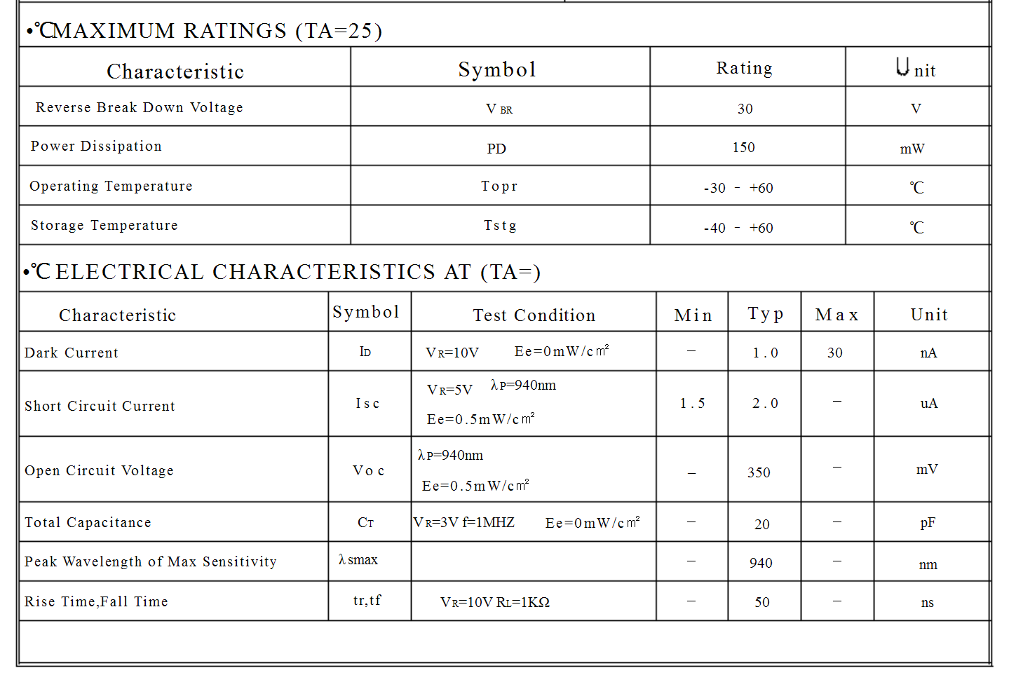
I would also be a bit suspicious of some of those numbers, there are data sheets for parts with similar part numbers that match except for some significant differences, for example, this Taiwan maker:

enter image description here

\$\endgroup\$

Your Answer

By clicking “Post Your Answer”, you agree to our terms of service and acknowledge you have read our privacy policy.

Not the answer you're looking for? Browse other questions tagged or ask your own question.