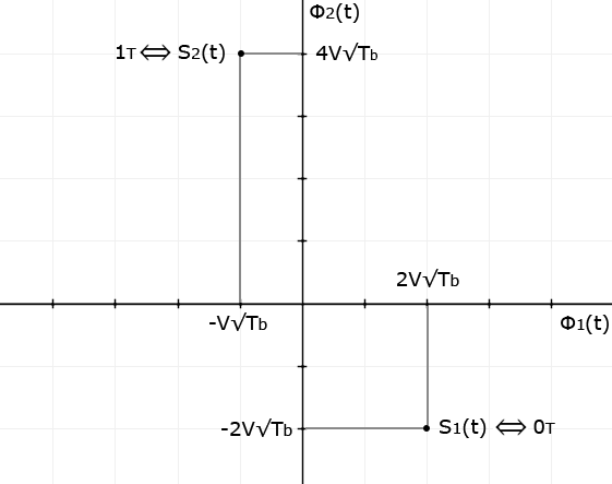
Constellation diagram of a communication system is given.


S1(t) -> 0, S2(t) -> 1
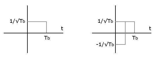
Φ1 and Φ2 are basis functions and Tb is the bit period.
How can I draw S1(t),S2(t) and decision boundaries?
Constellation diagram of a communication system is given.


S1(t) -> 0, S2(t) -> 1
Φ1 and Φ2 are basis functions and Tb is the bit period.
How can I draw S1(t),S2(t) and decision boundaries?
Let's see if I can guess how this is meant to be interpreted:
We have two basis functions, giving us a two-dimensional space in which to align symbols.
For successful decoding, the basis functions need to be at least linearly independent, and ideally, they should be orthogonal.
Testing for orthogonality, we multiply and integrate:
\$\int\Phi_1(t)\Phi_2(t)dt = 0\$
Good thing that worked, otherwise we would have had to prove \$\nexists x | \Phi_1(t) = x\Phi_2(t)\$.
For a two-basis system, that is somewhat sane, but with more basis functions, this starts to get really cumbersome. Fortunately, non-orthogonal systems are not that relevant in practice.
The amplitude is written in a manner that I find to be completely non-intuitive. Someone more enlightened than me could possibly comment on how that is useful beyond hinting at #7 below.
Constructing the time representation for each symbol is straightforward -- you multiply the symbol's constellation position with the basis function, and add these up (i.e. all you do here is a basis transformation of a vector):
\$S_1(t) = (2V\sqrt{T_b})\Phi_1(t) + (-2V\sqrt{T_b})\Phi2(t)\$
This system is equivalent to a Fourier transformation with two points. \$\Phi_1(t)\$ is the DC part, \$\Phi_2(t)\$ is the base frequency. Decoding this schema works likewise, by multiplying the basis function again, and correcting the linear amplification resulting from the integration (probably that's why the \$1/\sqrt{T_b}\$ is there).
The difference with the square waves is that you need to reconstruct the timing, which I assume is pretty much a given in that hypothetical scenario. If you don't have the timing information, the multiplication and integration become a full convolution, and you have to find the middle of the symbol.
The decision boundary would most likely be placed so that for each constellation point, the nearest valid symbol is selected. You have two valid symbols, so just draw a line in the middle between them.