4
\$\begingroup\$

I want to puild a pH meter, which uses a normal glass electrode. Such an electrode behaves as a pH dependend voltage source (<+-500mV) with very high internal resistance (10MOhm - 1GOhm, depending on the electrode). As a consequence, the voltage measurement needs to be performed with very low current. Further, I read that current flow can have a significant impact on the lifespan of these electrodes, so keeping it as low as possible is crucial.

I looked around and found a few promising amplifiers with input currents in the femtoampere range - e.g. the INA116, LMP7721, and LMC6001.

However, I'm wondering now how to protect these amplifiers against ESD, since the device will have to pass standard EMC tests for household appliances. Some of the amplifiers have limited protection built-in, but as far as I understand, this is not enough to protect against the tests that are performed on external device connectors. Adding diodes to the power rails or a TVS diode seems to be out of the question due to the substantial added leakage of even low-leakage types.

However, since the voltage source I want to measure has a very high resistance anyway, would the amplifier be adequately protected by a very high resistance (e.g. 10MOhm) series resistor? Or do I have to use a connector / electrode design which mechanically prevents direct contact?

\$\endgroup\$
1
  • \$\begingroup\$ Could you post your proposed schematic? \$\endgroup\$
    – Matt Young
    Commented Oct 13, 2014 at 14:43

5 Answers 5

2
\$\begingroup\$

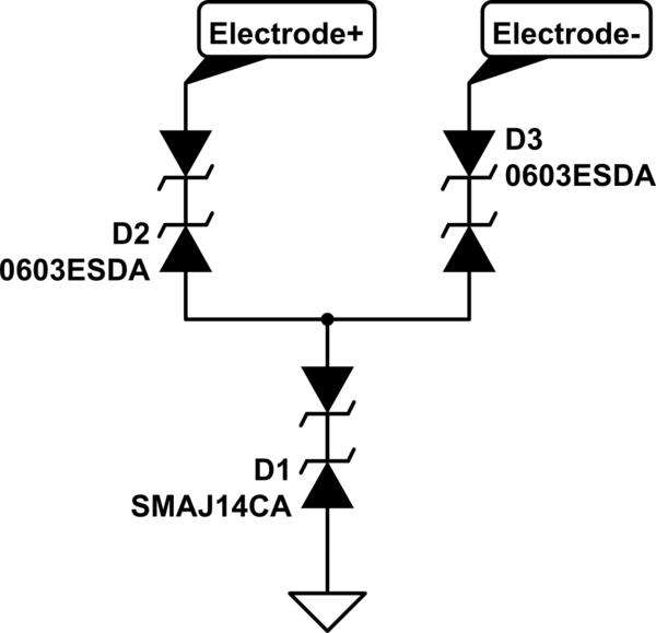
I've done some low leakage ESD protection recently. The scheme I used was fairly simple.

schematic

simulate this circuit – Schematic created using CircuitLab

It's hard to show in circuit lab, but there are only 3 components here. 2 0603ESDA bidirectional clamps, and 1 SMAJ14CA bidirectional TVS diode. The TVS has too high a leakage current on its own. The birectional clamps of a leakage current of less than 100pA typical. They keep the TVS out of the circuit until they clamp, and then the TVS takes over. It satisfied IEC61000-4-2 Level 4, criteria B.

\$\endgroup\$
8
  • \$\begingroup\$ Thanks - this might come in handy at some point. However, given the very high impedance of some pH electrodes I mentioned in my question, even 100pA could be significant (1 - 100mV, or up to 1.5pH values). I think by now though that a large resistor in front of the op amp input will be sufficient - 10 Megaohms would limit even a 20kV discharge to 2 mA, which is within the specs for the amp I want to use now - and at 4pA input bias max over temp for the op amp I chose, the error is 40µV max. \$\endgroup\$
    – Medo42
    Commented Oct 15, 2014 at 12:34
  • \$\begingroup\$ I have just come back to this because I'm looking at protection for some other input now, and now I wonder: Why is the SMA-diode even there? Wouldn't it be enough to directly connect the 0603ESDA diodes to frame ground? Maybe I misunderstand how the 0603ESDA's work... \$\endgroup\$
    – Medo42
    Commented Mar 3, 2015 at 11:35
  • \$\begingroup\$ @Medo42 For that application, I tried several different TVS diodes, and they had too much leakage current, but absorbed the hit. The 0603ESDAs had virtually none, but didn't absorb enough energy. Putting the two together was the magic bullet that gave me the protection I needed. \$\endgroup\$
    – Matt Young
    Commented Mar 3, 2015 at 13:56
  • \$\begingroup\$ There must be something I misunderstand here, because as far as I can tell, the SMA diode will only raise the clamping voltage at the electrodes. The ESD current will always have to go through one of the 0603s AND the SMA, so if the 0603s don't clamp the voltage well enough when connected directly to ground, how can they do so with an additional device in the current path? \$\endgroup\$
    – Medo42
    Commented Mar 3, 2015 at 14:05
  • 1
    \$\begingroup\$ @Medo42 It wasn't a matter of clamping. They just flat out don't absorb any of the energy. That's what the TVS was there for. I had a 2.5kV isolation barrier to maintain, and dumping the entire energy of the ESD hit into the ground plane caused all kinds of problems. I spent a month working on this issue, tried lots of different schemes and devices, and ended up with a product that passed level 4, criteria B. Take it or leave it. \$\endgroup\$
    – Matt Young
    Commented Mar 3, 2015 at 14:15
2
\$\begingroup\$

I don't know about PH sensors. I'd start by "cheating" and see how other people had done it. If you do end up needing a low leakage diode then you might want to look into using a small transistor. The c-b diode (open emitter) is low leakage (1-10 pA) but slow (100's of ns) The c+b - e (diode connected transistor, c/b shorted) is faster, but has a lower breakdown voltage. I've measured a few 2N3904/6's. and Bob Pease recommends the 2n930, 2N3707 and 2N4250. But you won't find these leakage number on the spec sheet. (For B. Pease reference search the web for B. Pease "Bounding and Clamping".)

\$\endgroup\$
1
2
\$\begingroup\$

You can use a simple RC network. A 10 meg resister and a 100 pF capacitor. The cap must be low leakage, a C0G/ 100v ceramic will do. With the right current limiting the op-amps own diodes will protect it.

\$\endgroup\$
1
  • \$\begingroup\$ This should be the accepted answer. However, note that not all OPAMPs have diode or similar devices connected from inputs to both supply rails. Confirm this fact in the datasheet of the selected OPAMP. \$\endgroup\$ Commented Dec 9, 2016 at 19:55
1
\$\begingroup\$

For reference: I ended up using the INA116 because it was designed specifically for this application, and because of its advertised built-in protection. For the ESD protection I first put a large value resistor in series with the inputs, similar to user68868's answer, but without a capacitor. In theory, the resistor should already limit the current to a tolerable level for the Op Amp's own protection circuitry, but I was concerned a high voltage ESD could also just arc over the resistor. To try protecting against that, I ran a guard trace between the two pads of the (0805, iirc) resistor, and didn't cover it with solder mask, the idea being that the discharge would then rather arc over to the guard rail. Then I put normal ESD diodes on the guard rails to protect those.

I'm sure I read about a technique like this somewhere, but I can't remember where that was anymore, and I also can't vouch for its effectiveness because this version of the circuit was never ESD tested. However, I thought it may be a good idea to have it here as inspiration :)

\$\endgroup\$
0
\$\begingroup\$

Quite old topic but I'll add my thoughts here. I'm using LMP91200 which has a guard net (same potential as input INP pin) so I'm considering adding resistor in series and C0G capacitor between INP and GUARD. Then some ESD diode to GND from GUARD and VCM pin. I was also thinking about gas discharge tubes. Littelfuse claims they have <1pA leakage current.

\$\endgroup\$
0

Your Answer

By clicking “Post Your Answer”, you agree to our terms of service and acknowledge you have read our privacy policy.

Not the answer you're looking for? Browse other questions tagged or ask your own question.