1
\$\begingroup\$

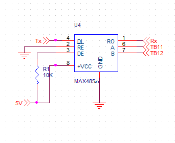
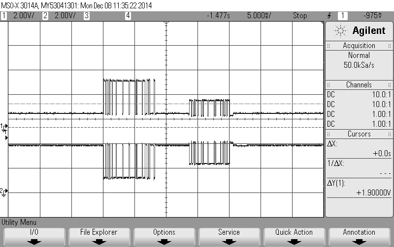
I've one system with rs485 with max485 chip with microcontroller (pin 2& 3 r connected to gpio).To access that system I've made one other system with ilx485 chip. Pins 2 & 3 of these are connected to gnd and 5v.when I'm connecting both system, I'm not able to receive the response from ilx485 one,but I'm getting echo of tx data. To debug this I've connected A and B to scope, transmit signal levels are close to 5v but for receive data signal levels drops to 3-3.5 v. I guess that's why it is not able to decode the receive signal to proper data. I've tried to use different cable, biasing resistors and terminating resistor. What seems to be the problem? Any suggestions?

Thanks in advance

EDIT -

Below is scope trace and RS485 board designed by me.

In the scope trace first train of pulse may be for TX data and second - RX data. As u can see voltage drops for RX signal.
Valid XHTML

Valid XHTML

\$\endgroup\$
2
  • 1
    \$\begingroup\$ A schematic could be useful... \$\endgroup\$
    – Cornelius
    Commented Dec 7, 2014 at 20:22
  • \$\begingroup\$ Any suggestions? \$\endgroup\$
    – ragdarbari
    Commented Dec 8, 2014 at 19:55

1 Answer 1

1
\$\begingroup\$

\RE can be held grounded, but DE should be driven high only when transmitting is in progress.

\$\endgroup\$
1
  • \$\begingroup\$ So basically we are looking at a tug-of-war between drivers, one which should be enabled at the remote end, and one at the local end which should not be enabled while expecting a reply, but rather only when transmitting. \$\endgroup\$ Commented Feb 10, 2015 at 3:43

Your Answer

By clicking “Post Your Answer”, you agree to our terms of service and acknowledge you have read our privacy policy.

Not the answer you're looking for? Browse other questions tagged or ask your own question.