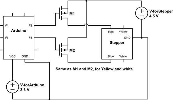
simulate this circuit – Schematic created using CircuitLab
Today I bought a stepper motor to play with, after 12 hours of struggling with it, I haven't been able to figure out how to connect it to an Arduino.
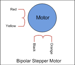
Is it okay if my stepper motor has exactly 4 wires?
Wires are colored: white, blue, red, yellow. All the pictures and circuits of easy tutorials I found on Google had 5 wires, (and those with 4 wires had different color coding anyway). But a 4-wire doesn't make sense! there must be 2 or 4 poles in a motor, and each pole needs a connection to common ground, so there must be 5 wires, how does a 4 wire work?
I'm using MOSFET for driving the stepper, not LMxxx
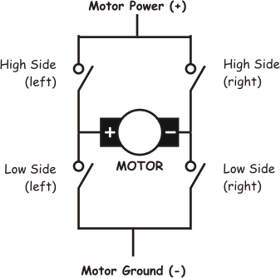
Because I forgot to buy one, and I can't get my hands on one for a couple of days. I use the MOSFETs as fast switches: 4 Arduino pins control 4 MOSFET transistors. And this is exactly the source of confusion: On arduino website, the sample circuit's stepper has 4 wires and is directly connected to a driver IC (a LMxxx), and the driver is connected to Arduino. Since I do not have a driver at hand, I need to convert the circuit so it works with 4 transistors instead. But what the wiring should be? If it had 5 wires I would have done it like this schematics.
It is very likely there are problems with my PNP/NPN Mosfet choice, but as soon as I know how to wire the circuit, I'll choose the right one!

