1
\$\begingroup\$

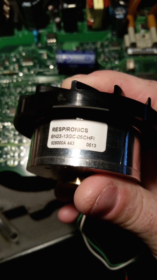
enter image description hereI have 2 blower motors. I know where they came from and what the models are but I cannot find any real info on them, and I don't know motors enough to know what I have or how to use them. I dabble in electronics a little but I am limited in certain aspects, stepper motors for example.

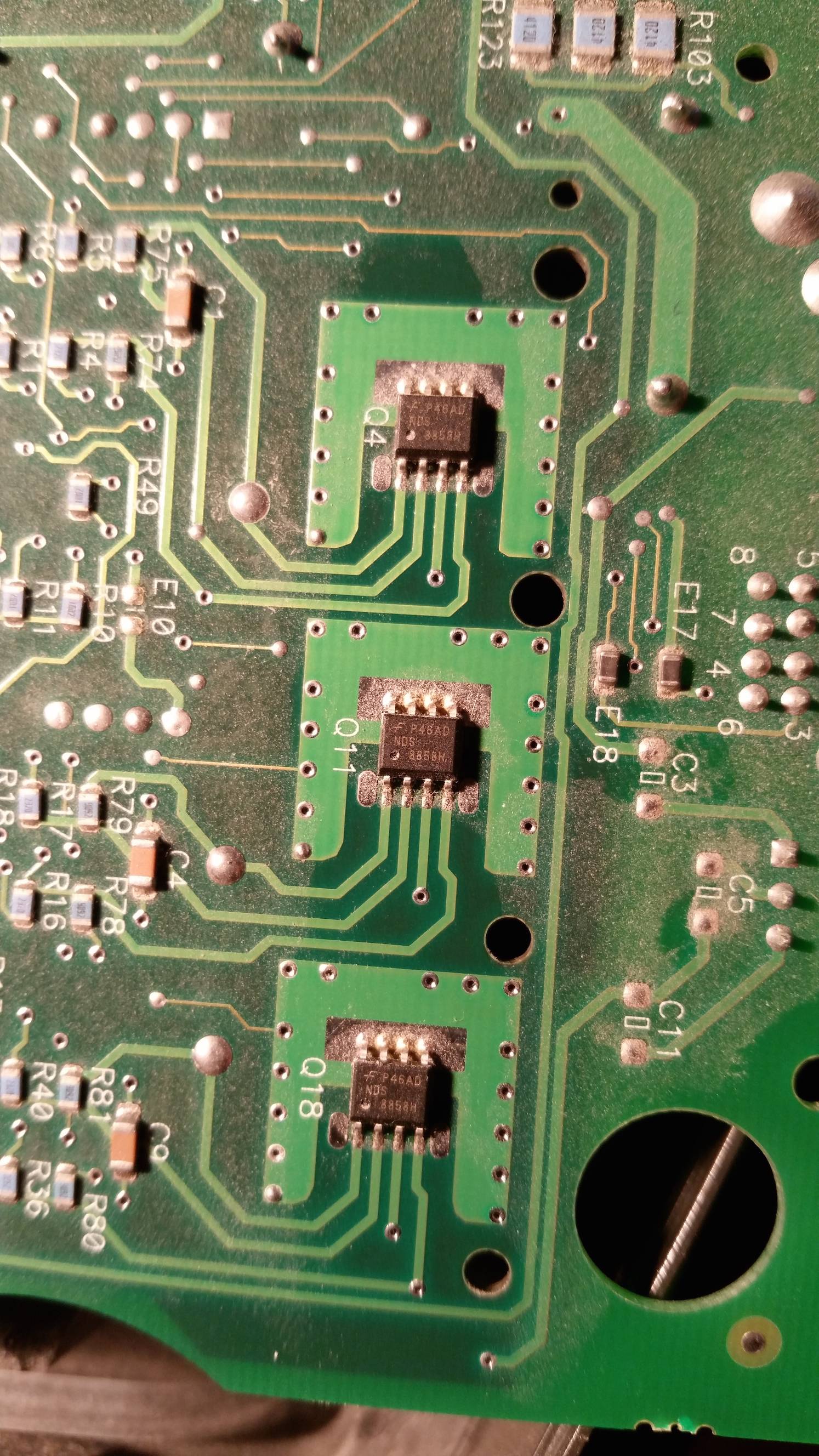
They are 2 blow motors from working REMStar Plus CPAP machines. I nabbed them in hopes I could use the blowers. I checked the voltage with my meter (in auto mode) coming off the green/black/white cable and all the pins fluctuated between 4.7-4.9 VAC no matter which pin combination I tested. I did not check the other smaller cable. The green/black/white cable appears to be the power, the other I think is for sensor data or something, it will run without the smaller harness plugged in. It looks like the motor comes off some NDS8858H chips, via google they appear to be mosfet half bridges?

What kind of motors are these (AC, DC, PWM, stepper etc)? How can I use them (what is required to talk to them, straight power or PWM etc)? I want to use them with an arduino or raspberry pi if possible. Thanks!

Here are some pictures.

This is the back of the board the motor connects to, the harness traces out (visually) to these chips. This is the back of the board the motor connects to, the harness traces out (visually) to these chips.
The motor The motor itself
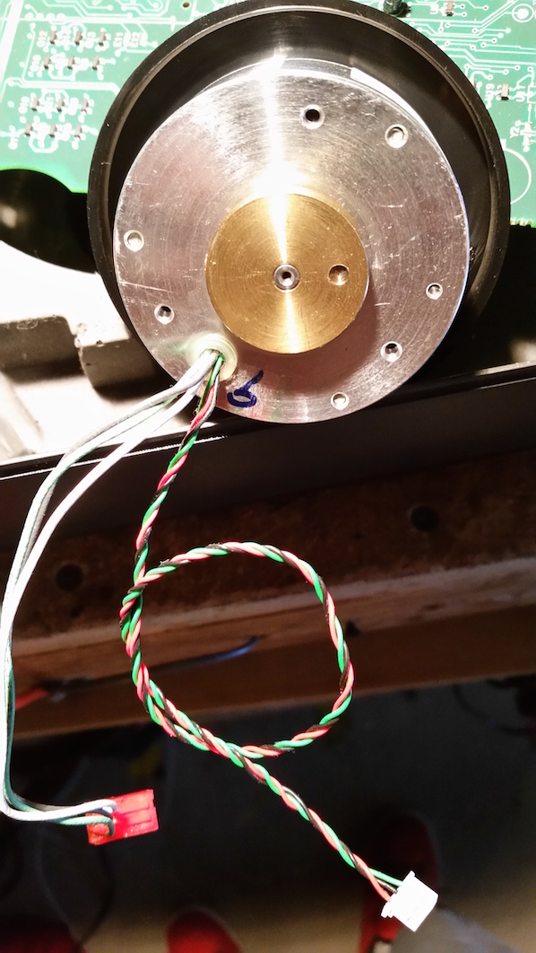
The side of the motor The side of the motor

\$\endgroup\$

1 Answer 1

3
\$\begingroup\$

It will be a Brushless DC motor, presumably with Hall sensors (the twisted cable).

Hopefully that should point you in the right direction in looking for a drive solution - there are many brushless DC drivers out there - sometimes called ESC's. But essentially they comprise of three half-bridges, one driving each phase. The Hall sensors feed back the rotor position to allow for correct timing when commutating the motor (switching phases digitally) without needing to resort to BEMF to determine rotor position which tends to be more tricky to do.

EDIT:

As Nick rightly points out I forgot about power when I was counting wires for the sensors. The twisted cables are probably some for of speed feedback. In this case you would need a driver which is designed to run BLDC motors which performs the commutation based on EMF from the motors.

\$\endgroup\$
3
  • \$\begingroup\$ Tom, I'm not an expert on brushless, but if the thin twisted wires are for the 3x Hall effect sensors, wouldn't there be more wires? Perhaps 4 or 5: sensors power, sensors ground, 3x sensors output. What's on the picture looks more like a single sensor: power (red), ground (black), sensor output (green). Could be a tachometer. \$\endgroup\$ Commented Jun 1, 2015 at 0:11
  • 1
    \$\begingroup\$ @NickAlexeev I think you are probably right about that. In which case the best approach would be an ESC or drive that uses BEMF for commutation. \$\endgroup\$ Commented Jun 1, 2015 at 0:24
  • \$\begingroup\$ @Marty, You should post your edit as an answer rather than editing this one. You can still find the changes is the edit history to copy out \$\endgroup\$ Commented Mar 8 at 9:13

Not the answer you're looking for? Browse other questions tagged or ask your own question.