7
\$\begingroup\$

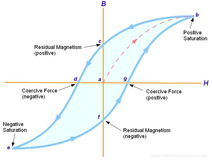
See the attached picture of a typical hysteresis loop, it is clearly highly non-linear even if you keep the signal small enough to stay out of the saturation region (beyond points b,e). So my question is why does this not result in a non-linear transfer function through the transformer from primary to secondary? Ampere's Law dictates that the H field generated is proportional to the current in the primary, so if I have a sinusoidal current as the input the graph below suggests that this will result in a B field which is a (non-linearly) distorted sinusoid and then the induced voltage in the secondary will be proportional to dB/dt, so it cannot be a sinusoid either, so an input sinusoid doesn't result in an output sinusoid and => the system is not linear. Yet transformers are routinely used in applications like audio where linearity is critical. So it seems that in general transformer transfer functions are linear but I just cant understand how they manage this given the Hysteresis effect, can anyone explain this ?

Thanks,
enter image description here

\$\endgroup\$
3
  • \$\begingroup\$ Just stay far enough away from saturation that things are linear for all practical purposes. \$\endgroup\$
    – PlasmaHH
    Commented Jun 29, 2015 at 12:23
  • \$\begingroup\$ who says it isn't distorted? \$\endgroup\$
    – user16222
    Commented Jun 29, 2015 at 12:40
  • \$\begingroup\$ who says it isn't distorted? – JonRB - Well 'PlasmaHH' right aboave your comment for a start, but also the fact that transformers are routinely used in audio applicaitons implies that their transfer functions must have very good linearity \$\endgroup\$
    – user261966
    Commented Jun 29, 2015 at 14:09

3 Answers 3

6
\$\begingroup\$

"the H field generated is proportional to the current in the primary" ... no, it's proportional to the difference between primary and secondary current (latter scaled by turns ratio).

So the nonlinearity only applies to the magnetising current. Now, if you drive the transformer from a finite source impedance, that nonlinear current translates to a nonlinearity in the voltage across the transformer itself.

Assume 10% nonlinearity from the region of the B-H curve we actually use, and the magnetising current is 10% of the total, the nonlinearity in the primary current is 1%.

Furthermore, assume the source impedance is 10% of the load impedance (scaled by N^2) and primary impedance in parallel, so that 10% of the driving voltage is developed across it by the total primary current: that 1% current nonlinearity results in 0.1% nonlinearity on the secondary voltage.

So a 10% B-H nonlinearity in this example results in 0.1% nonlinearity in the transfer function. And to reduce it further you can reduce the source impedance of whatever drives the transformer.

\$\endgroup\$
3
\$\begingroup\$

if I have a sinusoidal current as the input

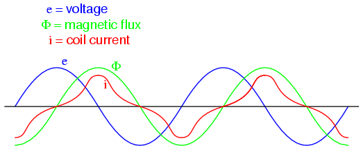
You don't normally have a current driven primary, you have a voltage driven primary and, as saturation starts to kick-in, you get a higher current than for an unsaturating primary. The two effects of increased current at the peaks and decreasing dB/dt (at the peaks) I guess will tend to resolve themselves to something like linear volts out. Here's a pretty picture from the web that supports this general idea: -

enter image description here

Note that current is not very sinusoidal yet flux, despite the non-linearity is seemingly sinusoidal. Here's what that site says: -

When a ferromagnetic material approaches magnetic flux saturation, disproportionately greater levels of magnetic field force (mmf) are required to deliver equal increases in magnetic field flux (Φ). Because mmf is proportional to current through the magnetizing coil (mmf = NI, where “N” is the number of turns of wire in the coil and “I” is the current through it), the large increases of mmf required to supply the needed increases in flux results in large increases in coil current. Thus, coil current increases dramatically at the peaks in order to maintain a flux waveform that isn't distorted, accounting for the bell-shaped half-cycles of the current waveform in the above plot.

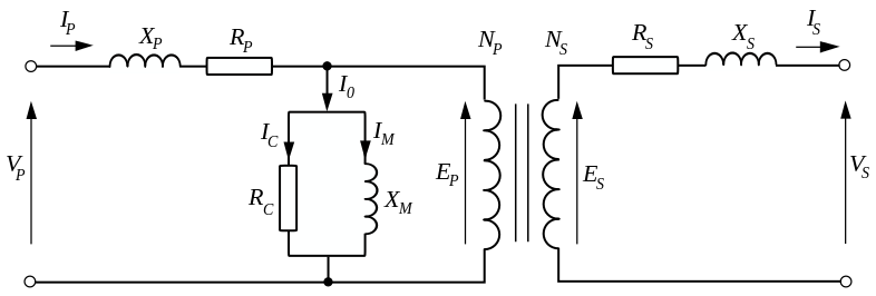
If you looked at the equivalent circuit of a transformer you'd see that any distortion in the magnetization current (providing input leakage components are relatively small and the input voltage waveform can be sustained in shape) won't affect the voltage across the ideal transformer: -

enter image description here

I\$_M\$ is the magnetization current and this current doesn't contribute to the creation of V\$_S\$ even if it is really badly shaped and peaky. Providing Rp and Xp don't generate too much of a volt drop (that would reflect the horrible shape of Im) then I think distortion will not be as bad as you believe it might be.

\$\endgroup\$
2
\$\begingroup\$

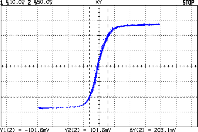
Compared to actual transformer behavior, the typical textbook hysteresis curve is highly exaggerated. See this page.

enter image description here

Of course we don't want to use the bits at the ends where it is saturating.

\$\endgroup\$

Your Answer

By clicking “Post Your Answer”, you agree to our terms of service and acknowledge you have read our privacy policy.

Not the answer you're looking for? Browse other questions tagged or ask your own question.