That's a crappy circuit. Don't believe everything you find lying around on the internet.
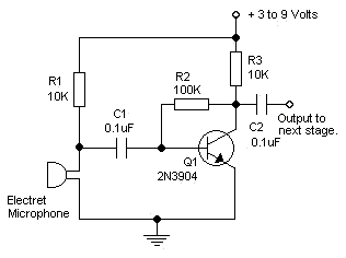
For reference, here is your circuit:

The 10 kΩ pullup to power from 3 to 9 V should be good enough for most electret microphones. C1 then feeds just the AC part of the microphone voltage to the amplifier stage. That's all fine.
The problem is the poorly designed biasing for this common emitter amplifier. The transistor will be on with only a little more than the B-E drop on the collector. This leaves little room for the output to swing low.
A quick bandaid for this circuit is to add another 100 kΩ resistor from the base of Q1 to ground. That with R2 will then form a voltage divider so that the collector DC voltage should be in the 1 to 1.5 V range. That leaves some room for it to swing both ways.
Another problem with this circuit is the unpredictable gain. The gain applied to the microphone signal has a high dependency on the gain of the transistor. In good transistor circuits, everything works well with the transistor gain from some minimum specified value to infinity.
Another problem may be the rather high output impedance of this amplifier, which is about 10 kΩ. That together with the sound card input impedance forms a voltage divider. If the sound card input impedance is 600 Ω, for example, then the signal will be attenuated by over 15x when connected to the sound card.


