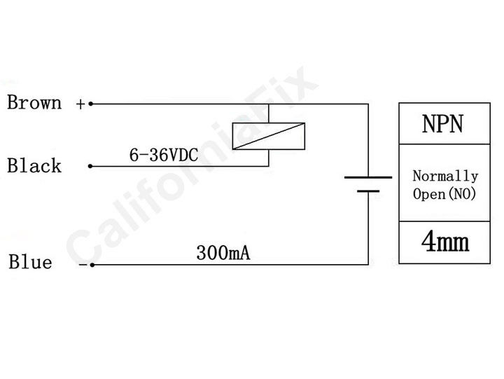
I'm trying to repair an old circuit based on the Micro-controller S87C751 interfaced with an inductive proximity sensor similar to one already posted here
The sensor is powered +24V.
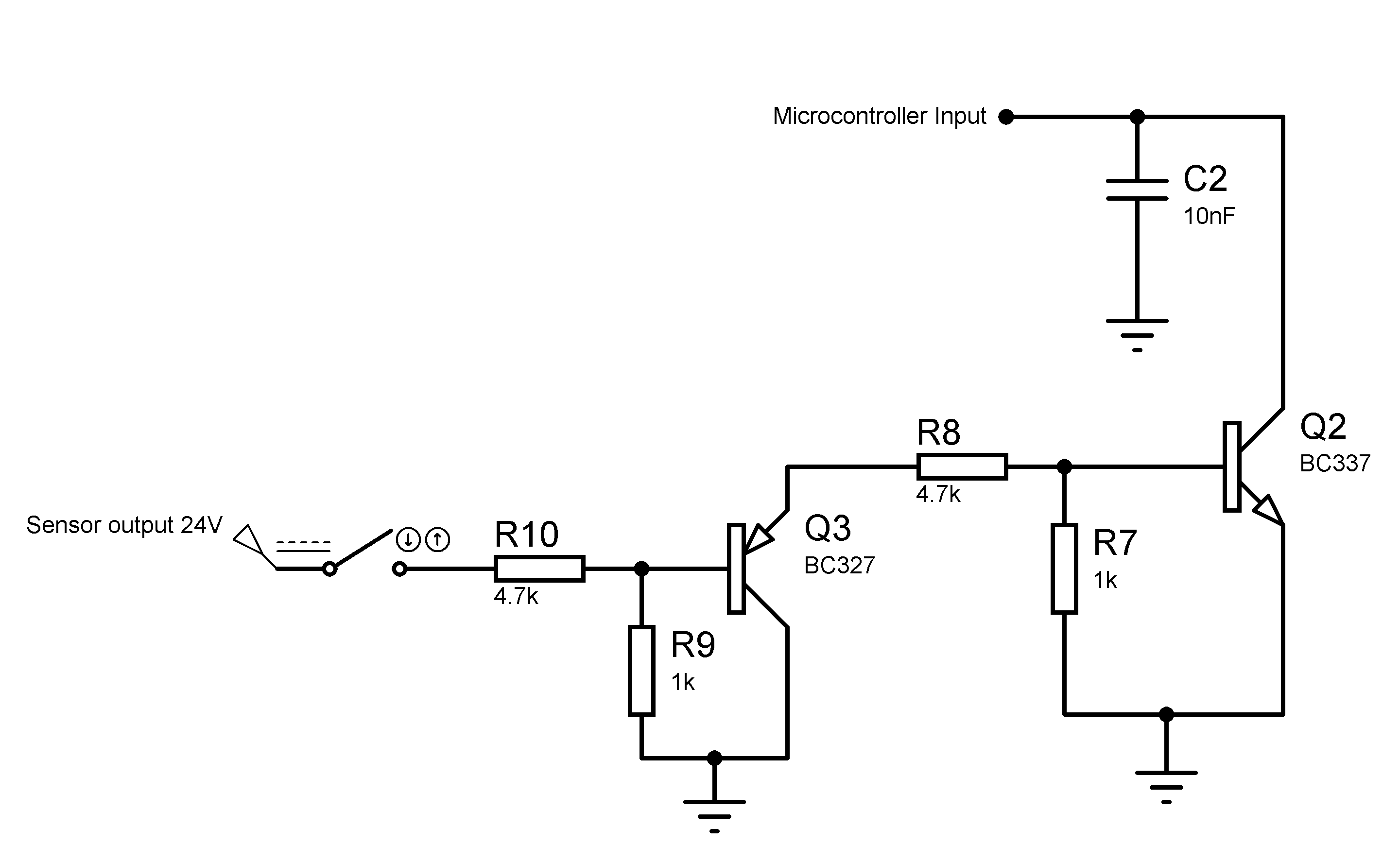
I followed the circuit paths from the sensor until the input of the Micro controller and i found it wired in the following way:
The uC is powered +5V.
As you can notice, the circuit designer used a PNP transistor combined with an NPN transistor.
My questions are:
1/ What is the purpose of this transistors combination ?
2/ Is it a level shifter ? if yes, is it really necessary ? As i already seen Arduino interfaced with such sensors with only a pull-up resistor not matter power source of the sensor.
3/ During simulation in Proteus ISIS, i simulated the inductive proximity sensor as a switch. the circuit didn't work, and i get always 0V at the uC input, what could be wrong with my drawing?
Thank you in advance for your help.
EDIT:
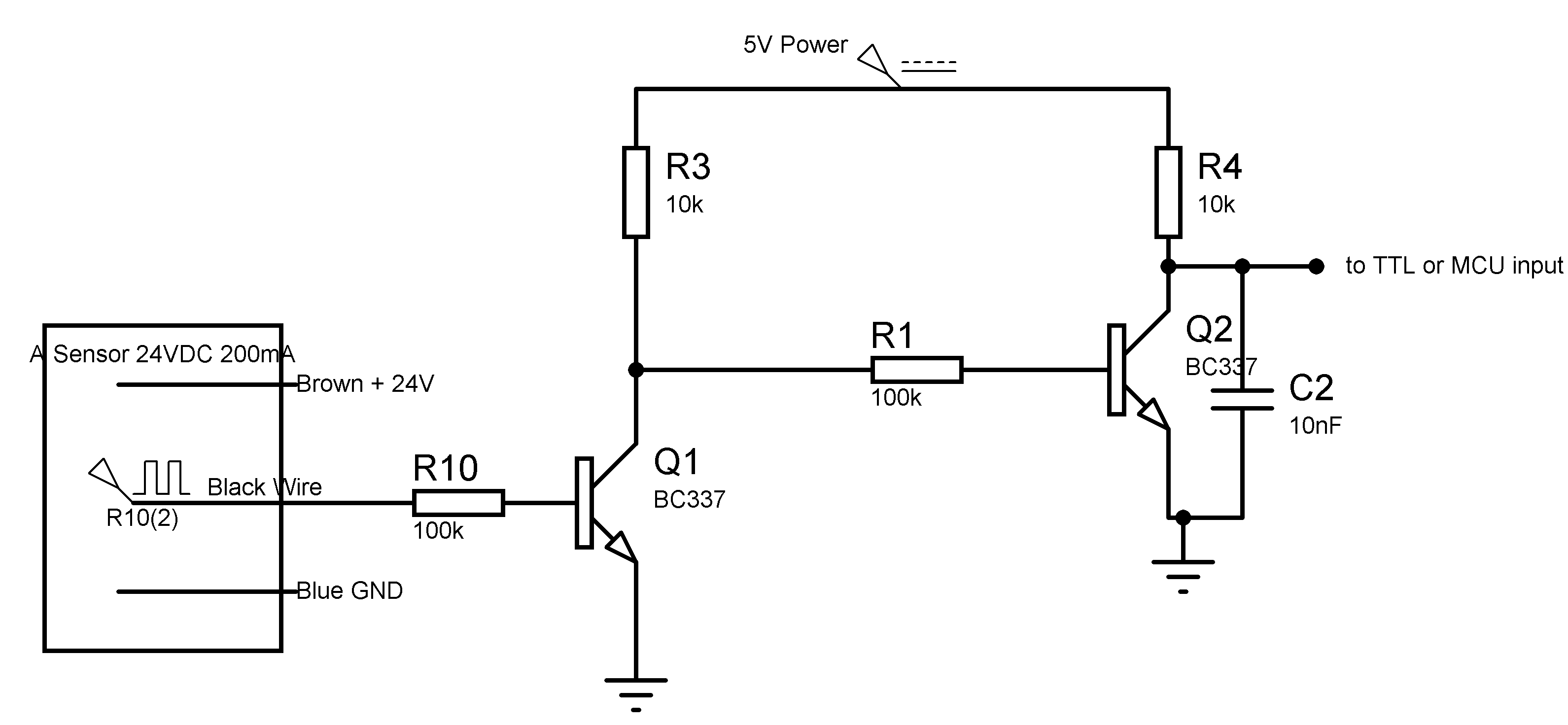
I plan to use the following level shifter using two NPN TRs instead of an PNP-NPN TRs, is it possible ?
I would like to include an LED in this circuit that gets ON when there is Metal detected to save one of the pins of the uC, how can this be possible? i tried including it however a voltage drop will occurs so i'll not get the 5V output.


