1
\$\begingroup\$

I have an +- 10V/1A sawtooth signal that needs to be clamped to gnd when a trigger pulse is received.

The signal is supposed to stay clamped until the next zero crossing, upon which the circuit is supposed to reset.

I thyristor would be ideal, if it did not have an on state voltage of typically 1.2V.

The voltage needs to be clamped below 400 mV, less is better.

The transition open -> clamped needs to be faster than 500 ns, preferably much less.
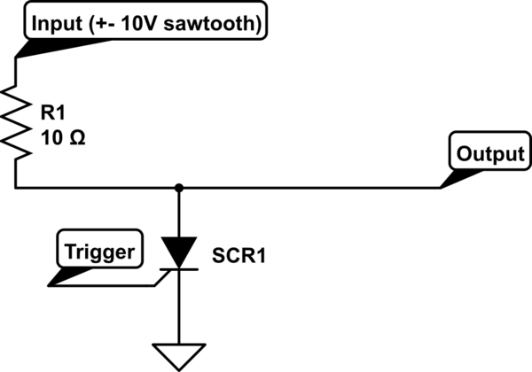
schematic

simulate this circuit – Schematic created using CircuitLab

Is there anything like a thyristor/triac (or a drop in replacement circuit), but with a much lower on-state voltage (below 400 mV)?

Edit: I came across a few devices I wasn't aware of. Doesn't help with my problem, but might be useful for someone else:

  1. Programmable unijunction transistor (Von voltage not clear from datasheet, maybe 500 mV + IR, obscure component)

  2. Silicon bilateral switch http://www.farnell.com/datasheets/239125.pdf (IC version of a triac, Von = 1.7V, Main advantage is very precise switching voltage)

\$\endgroup\$
7
  • \$\begingroup\$ As I understand it, when the trigger occurs you want to clamp (short) the output, which could be anywhere between plus or minus 10 volts, to ground and hold it there until the current through R1 falls to zero, at which time you want to release the clamp until the next trigger comes along. Is that right? \$\endgroup\$
    – EM Fields
    Commented Oct 30, 2015 at 10:24
  • \$\begingroup\$ What are the rise and fall times of the sawtooth waveform, and what release time for the clamp can you live with? \$\endgroup\$
    – EM Fields
    Commented Oct 30, 2015 at 15:36
  • \$\begingroup\$ @EM Fields. Correct, the output is shorted, and when the current falls to zero the clamp is released. The waveform has a rise time of around 100 us, the frequency varies a bit. \$\endgroup\$ Commented Oct 30, 2015 at 18:06
  • \$\begingroup\$ What about the fall time? \$\endgroup\$
    – EM Fields
    Commented Oct 30, 2015 at 21:13
  • \$\begingroup\$ fall time is similar. It looks roughly like a triangular wave. \$\endgroup\$ Commented Oct 30, 2015 at 21:49

1 Answer 1

1
\$\begingroup\$

A Thyristor or Triac drops ~1.2V because it needs some power to keep itself turned on. This property is also used to turn the Triac off at the zero crossing point (ie. when voltage drops below 1.2V).

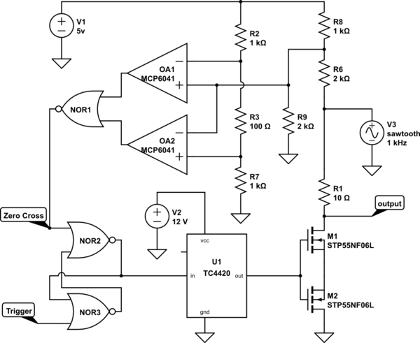
You could replace a Triac with back-to-back MOSFETs which have very low voltage drop at 1A, but you will need extra circuitry to detect the trigger pulse and zero crossing, and to drive the FETs. Something like this:-

schematic

simulate this circuit – Schematic created using CircuitLab

When a trigger pulse is fed into the R/S flip-flop formed by NOR gates NOR2 and NOR3, NOR2 toggles to a logic high output. The flip-flop will stay in this state even after the trigger pulse is removed. Gate driver U1 converts the 5V logic signal into a high voltage and current to turn the MOSFETs on quickly.

Op-amp OA1's output is high when the sawtooth wave is positive, while OA2's output is high when the wave is negative. R3 introduces a small bias voltage that causes both op-amp outputs to be low when the wave is close to zero Volts. When this happens NOR1 produces a logic high output, resetting the R/S flip-flop and turning the MOSFETs off.

But why do you need two FETs? MOSFETs have an inherent body diode that would conduct when the wave went negative, even when the FET was 'off'. With two FETs wired back to back the body diodes oppose each other, so one is always blocking this unwanted current path.

\$\endgroup\$

Your Answer

By clicking “Post Your Answer”, you agree to our terms of service and acknowledge you have read our privacy policy.

Not the answer you're looking for? Browse other questions tagged or ask your own question.