1
\$\begingroup\$

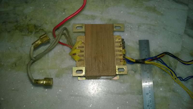
I have collected a big transformer from old UPS. I don't know this is step up or step down. I want to use it as step down transformer. One side has many 5 pairs of cable and another side has 3 cables. I want to convert 220V AC to 3-12V DC.

Edit (added photo)

I have attached photo of the transformer. enter image description here

\$\endgroup\$

3 Answers 3

3
\$\begingroup\$

A transformer can be both a step up or step down, it just depends on the turns ration and what you consider to be the primary and secondary windings.

What you can do is use a function generator to excite a set of windings and then measure the open circuit voltage on the others windings. This can allow you to estimate the turns ratio and see if transformer will work in your application.

This can give you a better description of how a transformer works and how to do the calculations.

\$\endgroup\$
2
  • 5
    \$\begingroup\$ However, if you use a step down (by design) transformer as a step up, you may exceed the insulation voltage on the windings. The other direction is not so much of a problem, though estimating safe current limits is always a bit of a challenge with undocumented transformers. \$\endgroup\$
    – Ecnerwal
    Commented Dec 19, 2015 at 15:38
  • 4
    \$\begingroup\$ A transformer can also be neither step up or down. \$\endgroup\$
    – Andy aka
    Commented Dec 19, 2015 at 18:36
3
\$\begingroup\$
  • The primary coil of the transformer will draw the same power from the mains supply as the load is drawing on the secondary plus a bit extra for losses.
  • Since P = V * I we can see that the high voltage coil will have low current and the low voltage coil will have high current.
  • Therefore, the low voltage coil will have thicker wires and fewer turns than the high voltage coil.

Be careful. Use fuses. Wear goggles.

[Update after photo added.] It's not possible to tell. There are no manufacturer's markings or labels on the wires. Options:

  1. Go back to the UPS and figure out where the transformer was connected and figure it out from there.
  2. Identify the coils on the transformer. Label each wire. Pick one wire and do a continuity test to every other wire. Write down what's connected to what - they're your separate windings. If you more than two wires in a group then measure the resistance between them and figure out which are the ends and which are the tap-off points. Probably both yellows are one coil, both blues another but why there's a bundle with blue, yellow, brown and red I do not know. There may be some centre-tap coils. Report your findings (in your question) in format "red - 7Ω - red", "yellow - 3Ω - brown - 3Ω - red", etc. or make a sketch and post a photo. e.g.,

schematic

simulate this circuit – Schematic created using CircuitLab

\$\endgroup\$
2
  • \$\begingroup\$ I have added a picture of the transformer. This could help you understand its type. \$\endgroup\$
    – palash
    Commented Dec 20, 2015 at 7:44
  • \$\begingroup\$ Update added after photo. \$\endgroup\$
    – Transistor
    Commented Dec 20, 2015 at 8:21
-1
\$\begingroup\$

even basing on the guage of the winding of the primary and secondary.. we can say the nature either it is step up or step down .. but using a step up transformer as step down one, effects the insulation of the other winding and vice versa

\$\endgroup\$
1
  • 2
    \$\begingroup\$ Poor answer. Please edit your answer to explain how insulation of the other winding is affected. Please also use proper capital letters and punctuation. \$\endgroup\$
    – Transistor
    Commented Dec 20, 2015 at 8:37

Not the answer you're looking for? Browse other questions tagged or ask your own question.