0
\$\begingroup\$

I am little confused in basic understanding of LCD interface.

Many times datasheet suggest 8/16 bits MPU interfacing. Here, for interface we assign GPIO's of microcontroller to respective data pins of TFT ( DB0 to DB7 or DB0 to DB15 depending upon 8/16 bits interface )

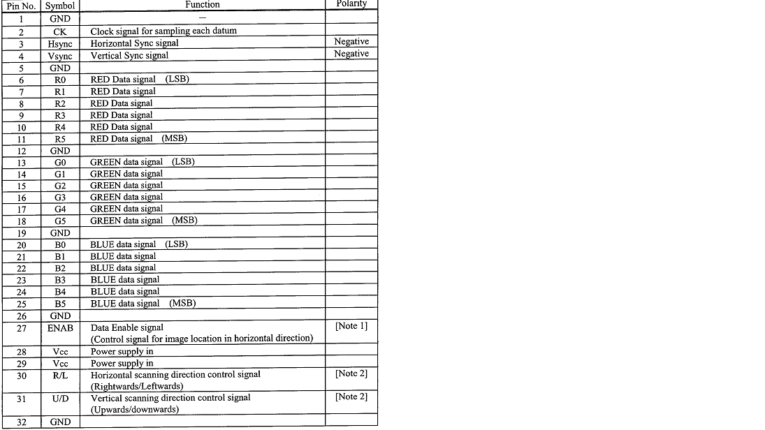
Sometimes in TFT datasheet, RGB interface is mentioned as per below screenshot.

RGB

Here, RGB pins of LCD are normal GPIO of controller or there is TTL to RGB converter needs to be added then interfaced to LCD?

What about HSYNC or VSYNC pins? Are they GPIO's only?

Please someone explain. Thanks.

\$\endgroup\$
2
  • \$\begingroup\$ Can you add the reference of the part you're referring to? \$\endgroup\$
    – user59864
    Commented Dec 22, 2015 at 12:42
  • \$\begingroup\$ avnet-embedded.eu/fileadmin/user_upload/Files/Displays/… please refer lcd datasheet's link. It's 8.4" with 18 Bits RGB.So, RGB pins and HSYNC and VSYNC are GPIO (digital) pins only? \$\endgroup\$ Commented Dec 22, 2015 at 13:54

1 Answer 1

3
\$\begingroup\$

The datasheet of the LCD tells you the signals that must be present on the LCD interface pins. How you achive that is up to you, you can bit-bang the signals on GPIOs, use an-on chip or off-chip LCD controller, a custom-programmed FPGA, or even black magic. The LCD doen't care.

In most cases, the 8/16 bit interfaces (and for smaller LCDs, SPI or I2C interfaces) talk to some kind of controller on the LCD. The communication is in terms of instructions, like "set these pixels to black". This kind of interface can easily be done by the CPU (using bit-banging)

In most cases, interfaces that mention RGB line and SYNC signals interface more directly to the LCD: they specify the full data that must be displayed, and this data (a frame) must be repeated at the frame rate (typically 10..100 Hz). This requires much more attention from the CPU if it would do it all by its own, and for larger LCDs this is totally impractical. (Where the switchover point lies depends on the CPU, programmer skills,a nd CPU time needed for the rest of the application.) These type of LCDs are generally interfaced via an on-chip LCD controller.

\$\endgroup\$
6
  • \$\begingroup\$ In case of LVDS LCD interface, do we need lvds transmitter and receiver both or Flow will be RGB Digital lines from MPU-->RGB to LVDS converter--->LVDS pin of TFT? Which is correct? \$\endgroup\$ Commented Dec 22, 2015 at 14:44
  • \$\begingroup\$ Which 'we'? If an LCD requires LVDS signals you must create those voltages. If for instance, your FPGA or whatever you have outputs LVDS directly you need no translation at all. \$\endgroup\$ Commented Dec 22, 2015 at 15:05
  • \$\begingroup\$ Thanks... but in which case rgb to lvds and lvds to rgb interface used? \$\endgroup\$ Commented Dec 22, 2015 at 15:25
  • \$\begingroup\$ when you want the long lines (eg. flex cable in a laptop) to be at lvds level. \$\endgroup\$ Commented Dec 22, 2015 at 15:35
  • 1
    \$\begingroup\$ How should I know? I don't have that setup on my desktop. Check out the lvds specs, the specs of your cable, and see if it matches. Or as a new question about lvds cable lengths. \$\endgroup\$ Commented Dec 22, 2015 at 16:13

Your Answer

By clicking “Post Your Answer”, you agree to our terms of service and acknowledge you have read our privacy policy.

Not the answer you're looking for? Browse other questions tagged or ask your own question.