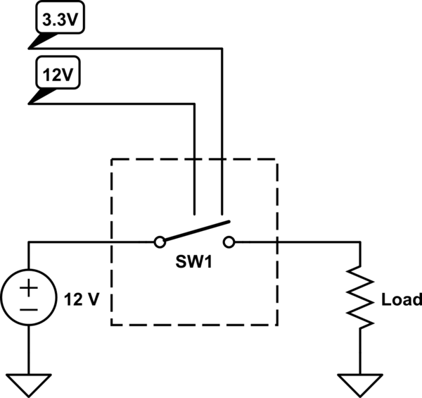
I need a switch, but with a small twist. If it was operating on normal filtered DC I would know how to make one myself. But since it's for a car, I need help designing it for reliability and surge protection.
The most complicated thing about it will be the description, so please bear with me. Basically, what I need it is a switch with two independent control inputs. Input is active when there is voltage on it as described below, and inactive when there's no voltage (it'll be floating, not grounded). The switch should be shorted when either of the inputs is active, or both.
- Control input #1 is from the car's power grid, which means 10 V to 15 V DC + noise and voltage spikes. They say the spikes can be up to 100 V, and can even have reverse polarity, and it's my main difficulty with this design - I don't know how to make the circuit work reliably in these circumstances.
- Control input #2 is filtered 3.3V, so that one shouldn't be a big problem.

simulate this circuit – Schematic created using CircuitLab
What the circuit will be switching is also the car's power grid, so I don't know if I can use a MOSFET, for example - will it withstand a 100 V surge, which can have forward or reverse polarity? Current is 2 A with short peaks up to 3 A. The main +12 V input is always present, while the +12 V control input will appear and disappear.
It so happens that I also need to feed the 12 V control input that this circuit receives to a micro-controller's input, meaning I need to scale it down to +3.3 V or +5 V, and I need to remove the noise and voltage spikes in order to protect the MCU and detect the voltage reliably. So it will be beneficial if this switch will somehow filter and downscale the noisy input so that I can feed it to the MCU with no additional circuitry. Or at least filter out the noise so that I can connect the MCU's input via a MOSFET or an opto-isolator without the risk of this MOSFET / isolator being damaged by a voltage spike.
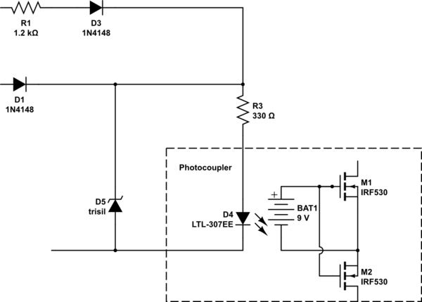
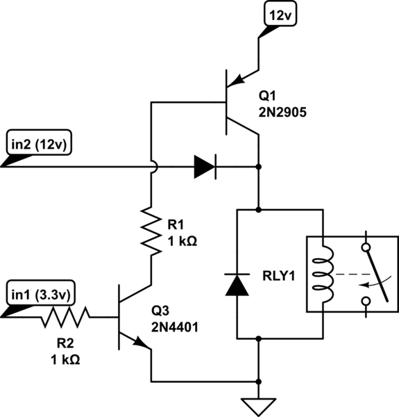
My original idea was 2 parallel MOSFETs with high enough gate-to-source voltage tolerance so that it can throughput 15 V while being driven by 3.3 V. And then I have to devise some kind of a filter for the MOSFET that's driven by the car's power grid, but I have no good ideas on how to do it both reliably and simply (with as few elements as possible). Maybe, a voltage regulator, like LM817? Will it withstand the voltage spikes? Will, like, a high-speed diode bridge for normalizing the polarity and an LC-filter do the trick? Also, I do not know if a MOSFET will withstand the car's voltage being passed into the source-to-drain channel, with its dual-polarity voltage spikes.


