1
\$\begingroup\$

I am using a 13mv input on a LM324 op amplifier. I am trying to get a gain of about 384 to 5 volts. I am not getting any voltage on the output?? Can anyone offer any suggestions why this circuit doesn't work or point me in the right direction. I have attached a schematic which I hope you can follow. Any advice would be appreciated.

Many Thanks
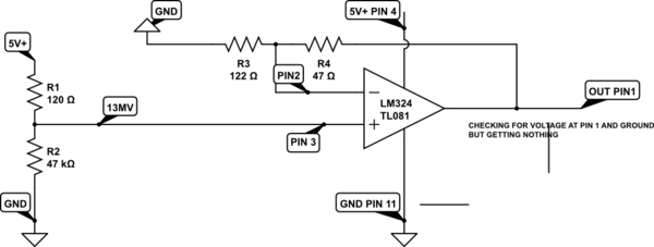
schematic

simulate this circuit – Schematic created using CircuitLab

\$\endgroup\$
5
  • \$\begingroup\$ Your feedback resistors are very low. Try bigger values. \$\endgroup\$
    – Marco
    Commented Jan 24, 2016 at 21:29
  • 3
    \$\begingroup\$ Apart from that 120 Ohm from 5V and a 47kOhm to ground will not get you 13mV. Also it's mV, not MV, that's Mega Volt. Further the 324 will not give you 5V out, once these things are fixed on a 5V supply. A normal op-amp can't go to within less than 1V of its supplies. I believe a 324 can go very close to pin 11, but at least 1V away from Pin4, possibly even 2V. \$\endgroup\$
    – Asmyldof
    Commented Jan 24, 2016 at 21:33
  • \$\begingroup\$ R4 is really 47K ohms, not 47 ohms, right? And you've swapped the values of R2 and R1 if you want to get ~13mV. I would expect you to get ~4V out with this circuit (previous assumptions included), typically, so something else is wrong. Maybe you destroyed the chip or it isn't actually getting power. \$\endgroup\$ Commented Jan 24, 2016 at 21:54
  • \$\begingroup\$ The R1/R2 voltage divider will give you 4.987 volts - exchange the values of R1 and R2 to get 13 mV. \$\endgroup\$ Commented Jan 24, 2016 at 22:00
  • \$\begingroup\$ Thanks for the replies. I will try a new chip. Thanks for pointing out R1 and R2. \$\endgroup\$
    – Michael
    Commented Jan 24, 2016 at 23:16

1 Answer 1

1
\$\begingroup\$

By the first look it looks like you are sourcing to much current out of your opamp:

I = 5V / 47Ω ≈ 100mA

Gives you 100mA maximal output current but the LM324 is only capable of delivering 20 - 40mA.

Try with bigger values like:

R3 = 122kΩ
R4 = 47kΩ

EDIT: Ok your resistor values are wrong too. The gain of your circuit is:

gain = (R4 / R3) + 1 = 1.4

And not 384.

EDIT2:

As others have pointed out you can't expect 5V on your output because the LM324 is not capable of driving the outputs close to its power rails.

\$\endgroup\$
7
  • \$\begingroup\$ Also it looks like the input might have a large DC bias on it. Not sure because it looks like a resistor divider from a 5V supply, not sure where or why it should be 13mV. May need a capacitor to couple the AC component and some DC bias path on the non-inverting input. As previously mentioned the supplies will not allow 5V output, the gain is wrong and it's not clear what bandwidth is required. \$\endgroup\$
    – John D
    Commented Jan 24, 2016 at 21:54
  • \$\begingroup\$ Thanks for the reply. Obviously there are a few issues which I need to address. My main concern is I thought I had worked the gain out right. R4/R3=(47000/122)= 384+1. I will do some research on calculating the gain. I do have 13mv from the voltage divider?? \$\endgroup\$
    – Michael
    Commented Jan 24, 2016 at 22:10
  • \$\begingroup\$ Maybe you calculated the gain right but looking at your drawn schematic it's obviously wrong. \$\endgroup\$
    – Marco
    Commented Jan 24, 2016 at 22:12
  • \$\begingroup\$ And no, you do not have 13mV on your input: you have roughly 4.98V. (5V / (120 + 47kΩ)) * 47kΩ ≈ 4.98V \$\endgroup\$
    – Marco
    Commented Jan 24, 2016 at 22:12
  • 1
    \$\begingroup\$ Sorry just noticed the schematic is wrong r4 should be 47k not ohm. \$\endgroup\$
    – Michael
    Commented Jan 24, 2016 at 22:34

Your Answer

By clicking “Post Your Answer”, you agree to our terms of service and acknowledge you have read our privacy policy.

Not the answer you're looking for? Browse other questions tagged or ask your own question.