0
\$\begingroup\$

This is a non-inverting first order low pass filter.

The cut of frequency= 1591.5 Hz

The input frequency = 264.2 Hz

The input voltage = 1.5 Vp-p Sinewave
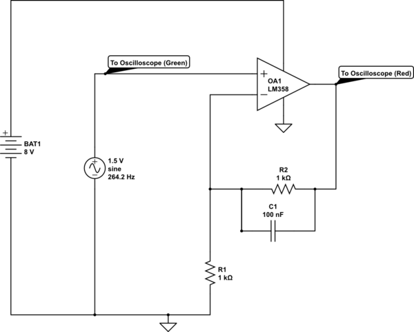
schematic

simulate this circuit – Schematic created using CircuitLab

According to this equation:

enter image description here

Af = 1+ R2 / R1

Af = 2

voltage gain Av at 264.2 Hz and 1.5 volt is 1.97 volts.

Output voltage = 1.5 * 1.97 = 2.95 volts.

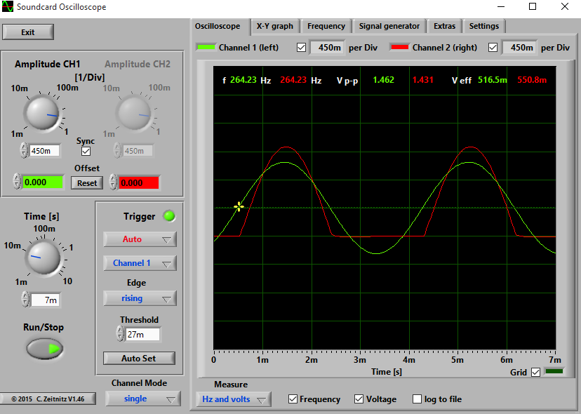
I tried to measure thes values: enter image description here The output voltage is only 1.431 volts!! and a distortion happened to the wave form. Why does that happen?
Thank you very much,

\$\endgroup\$

2 Answers 2

4
\$\begingroup\$

The bottom distortion is trivial to explain - you appear to be running the op-amp between 8+V and ground, you have not created a virtual ground at +4V, and so the signal is naturally clipping where the op-amp has no power to drive it.

For a simple approach, add a second battery to provide a -8V rail, if using 8V batteries, and power the negative power pin of the op-amp from that. Ground stays where it is, the + of the new battery connects to it, and the - of the new battery connects to the op-amp's negative power pin (not the inverting input - the one you currently show going to ground.)

The op amp is probably also feeling somewhat abused by having the inputs driven below the negative power rail in your current circuit - most (nearly all) op-amps are not fond of having an input that exceeds the power rails.

\$\endgroup\$
1
  • \$\begingroup\$ THE LM358 has an input absolute maximum (negative at the inputs) of -0.3V referenced to V-. If this is not limited to <50mA, it could very well be damaged, and I see no limiting from the signal generator. Good point about overdriving the input. \$\endgroup\$ Commented Feb 7, 2016 at 16:34
3
\$\begingroup\$

Your input voltage is an AC waveform which oscillates above and below the zero volt / ground line. It should peak at about +0.75 V and -0.75 V.

Your op-amp has its negative terminal connected to ground. The lowest voltage it can possibly output is 0 V and most will only get within a volt or two of that.

The fix

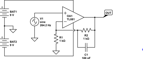
Power your op-amp from a dual supply, +8 V and -8 V or similar.

schematic

simulate this circuit – Schematic created using CircuitLab

Figure 1. Dual rail supply.

\$\endgroup\$

Your Answer

By clicking “Post Your Answer”, you agree to our terms of service and acknowledge you have read our privacy policy.

Not the answer you're looking for? Browse other questions tagged or ask your own question.