0
\$\begingroup\$

I have recently started learning to use pic micro controller. I am using pic16f887 mc and for programing using mplabx with xc8 compiler. My micro controller is getting reading from switch and turning on led when I use any digital i/o pin except rb0-rb5. I don't know why those pins are not working. I made the circuit in proteus also.It is giving me the same result. Can anybody tell me why this is happening? Here are codes and schematic where I used rc7 for input and that works perfectly.

void main(void) {
OSCCON=0x76;
TRISC7 = 1; //RC7 as INPUT PIN
TRISD1 = 0; //RD0 as OUTPUT PIN

RD1 = 0; //LED Off

while(1)
{
 if(RC7 == 0) //If Switch Pressed
 {
    __delay_ms(100);
    if(RC7==0)
    {
        RD1 = 1; //LED ON
        __delay_ms(3000); //3 Second Delay
          RD1 = 0; //LED OFF

      }

    }
  }
 return;
}
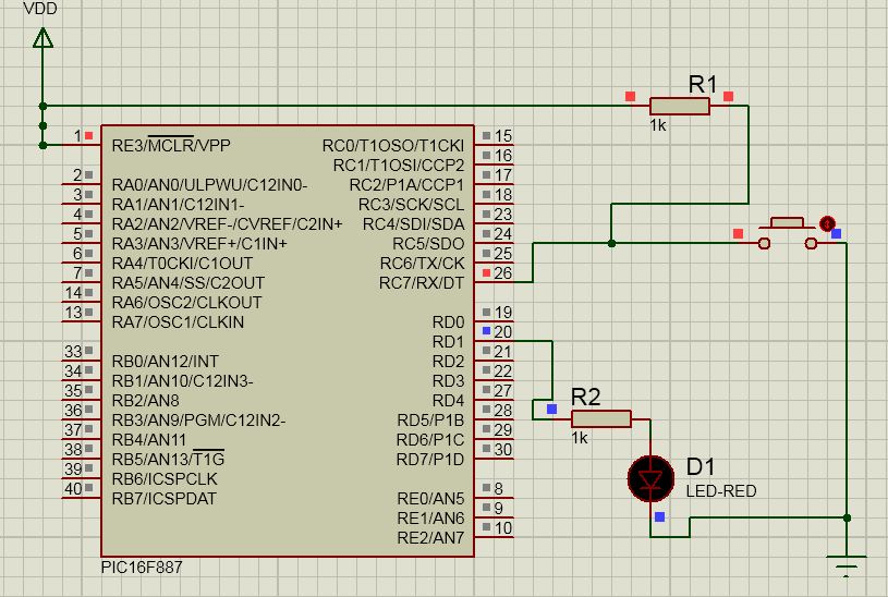
pic

\$\endgroup\$
8
  • \$\begingroup\$ I see you have defined RD0 as input but don't use it. I don't see where you have defined RC7. \$\endgroup\$
    – Transistor
    Commented Mar 17, 2016 at 14:42
  • \$\begingroup\$ From the comments on lines 3-4 I am guessing the TRIS registers were set wrong. Please show the non-working code that uses RB0-RB5. \$\endgroup\$ Commented Mar 17, 2016 at 14:52
  • 1
    \$\begingroup\$ I'm guessing that you haven't disabled the analog mode on those pins. The PIC powers up with them set as analog inputs and you have to set them as digital using the ANSEL registers. Have you tried any of the RA pins - you should have the same trouble there if you don't configure the ANSEL correctly. \$\endgroup\$
    – brhans
    Commented Mar 17, 2016 at 14:57
  • \$\begingroup\$ On the PICs I've worked with (18F4685), an input requires the TRIS bit to be set to 1, while an output is '0'. \$\endgroup\$
    – A.Mac
    Commented Mar 17, 2016 at 16:20
  • \$\begingroup\$ @transistor Sorry i commented wrong. RD0 is output pin. I have used that. RC7 is code for the trisc7 register .We don't need to define it. \$\endgroup\$ Commented Mar 18, 2016 at 2:07

1 Answer 1

1
\$\begingroup\$

Pins with analog inputs are set to analog input mode by default. To read a digital input you must clear the corresponding ANSEL or ANSELH bit. RB0 is AN12, so you need to clear ANS12 (bit 4 in ANSELH).

Pins set to output mode are not affected by the analog input settings. However a read-modify-write operation may fail if it needs to know the pin state and the pin is set to analog input mode.

\$\endgroup\$

Your Answer

By clicking “Post Your Answer”, you agree to our terms of service and acknowledge you have read our privacy policy.

Not the answer you're looking for? Browse other questions tagged or ask your own question.