How is the trick in the following video possible?
-
5\$\begingroup\$ For those who can't be bothered to click on the link: In the video 9 V battery is connected to a series circuit consisting of a resistor, 3 switches and 3 LEDs. When one switch is in on state, a single LED turns on even if other switches are in off state. \$\endgroup\$– AndrejaKoCommented Dec 20, 2011 at 7:26
-
2\$\begingroup\$ Most likely an edited trick video. There are other videos that show the same "trick" with two LEDs in series, or with LEDs in parallel. \$\endgroup\$– supercatCommented Dec 20, 2011 at 7:29
5 Answers
The Solution Revealed!
Hackaday summarizes:
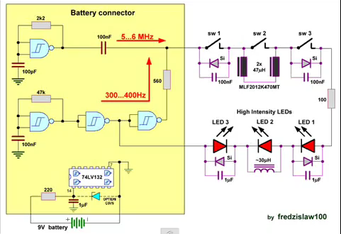
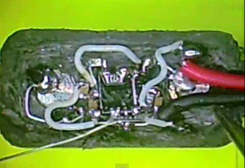
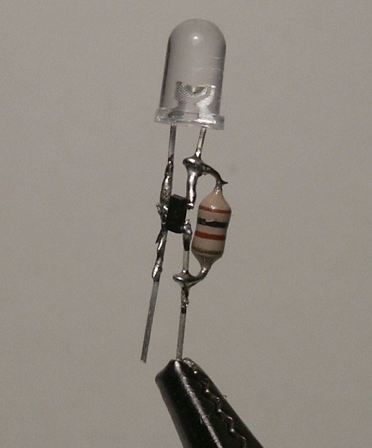
it uses two AC power sources, diodes, and inductors. In contrast to every single guess about where the circuit is hidden, the majority of the build is inside the battery connector. [Fredzislaw] did some amazing work hiding a 74LV132 quad NAND Schmitt trigger inside the battery connector. The diodes were easily hidden on LEDs 1 and 3 with some red nail polish, but we’re amazed by the inductor built into the LED seen in the title pic.
And two shots from the video, showing the circuit diagram and how it's embedded in the battery connector:


IF the switches are simple series SPNO switches as shown and
IF the LEDs are standard LEDs then by definition it is not possible - he is using video fakery and the demo is less than valueless.
"Not possible" is able to be said with certainty because examining even SW1 + SW2 + SW3 in series current can flow only when all 3 are operated.
HOWEVER if the "switches" and "LEDs" are modified then it is possible and it becomesa conjuring trick with rigged props. Still pretty pointless, but possible.
One of various ways:
Each switch contains a current determining circuit.
Each LED contains a window comparator and current bypass circuitry
LED1 lights for I1 or (I1 + I2) or (I1 + I3) or (I1 + I2 + I3)
eg say I1 = 10 mA, I2 = 20 mA, I3 = 40 mA.
LED 1 will light at 10, 30, 50 and 70 MA LED2 will light for 20, 30, 60, 70 mA LED 3 will light for 40, 50, 60, 70 mA
So
mA LEDS lit
10 001
20 010
30 011
40 100
50 101
60 110
70 111
Hopefully that table looks familiar.
There are many other trick ways and it is more likely that the system is "a trick". .
UPDATE:
Professors cam be liars and magicians also, apparently :-).
Again - AS LABELED this breaks the laws of Physics, it's a trick, something special is being done.
Here is a very long HackADay discussion on this exact topic by many people. Nobody there is certain how it is done, but some have more ideas than others.
If an excessively enthused person will pay me $1000 and I'll deliver you an essentially identical or better demonstration by end of this year. Pay me nothing and I just may do so anyway :-).
But, be certain, "It's a "magic" trick" [tm] using electronics as its medium. As long as you are aware of that aspect the actual how is unimportant.
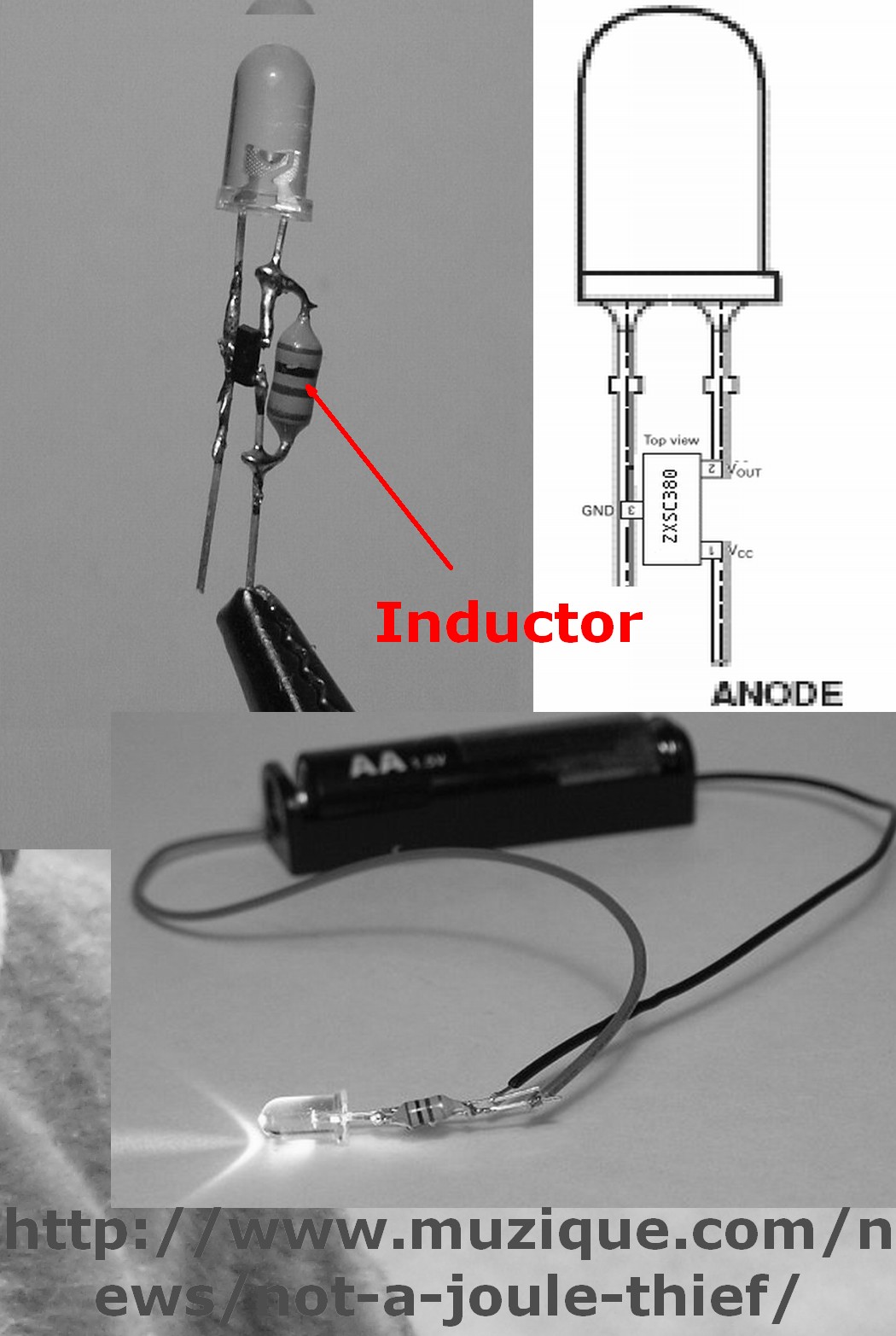
Found today in passing.
Inline LED driver

While this by itself does not fi=ully answer the problem it shows what can be done:

-
2\$\begingroup\$
Each LED contains a window comparator and current bypass circuitry: Are there LEDs like that that seem like in the video, or are you just saying "if there were"? \$\endgroup\$ Commented Dec 20, 2011 at 10:27 -
3\$\begingroup\$ An excessively enthused magician may make devices that look like LEDs but have extra circuitry. That's only one option. Doing so as shown is entirely possible but seems like too much work. Video fakery is the most likely option. Induction through the table in some manner is possible. Contacts somehow are also possible. | He presents it as science and engineering but its actually stage magic. That makes him a liar and a cheat as he will confuse learners with his lies. I have commented "robustly" on his video. I wonder if he will respond. | I cold do something equivalent if paid to do it :-). \$\endgroup\$– Russell McMahon ♦Commented Dec 20, 2011 at 11:30
-
\$\begingroup\$ @RussellMcMahon I have seen this "trick" done in person (by a EE professor), there is no video tricks at all. \$\endgroup\$– KellenjbCommented Dec 20, 2011 at 13:52
-
-
\$\begingroup\$ @Majenko I was going to add more to my comment earlier, but got distracted (ooooo shiny)... anyways, I have no idea how it is done, the professor said that we would have the ability to do the trick by the time we graduated, but I am graduated and still don't know how it is done :-) But since I saw it in person I can say that it isn't video tricks. My professor did it with regular incandescent light bulbs, and showed us that the bulbs were normal. \$\endgroup\$– KellenjbCommented Dec 20, 2011 at 14:06
Here is a possible solution to the series puzzle.
Three self powered oscillators, one in each switch (think small watch battery + 2 transistor multivibrator), each on a different frequency inductively coupled to the loop formed by their secondaries, and the secondaries of the three "leds".
The three leds are tuned circuits (think simple crystal set with the diode in this case being a genuine LED) inductively coupled to the loop, to pick up the frequencies being propagated round it by the three oscillators.
The battery is genuine enough, but it does nothing, since the battery snap is insulated, and has the red and black wires joined together, to complete the loop.
It might require some carefully hand wound inductors, or possibly off the shelf smd rf transformers. (Like these for example http://www.entheo-electronics.co.uk/components.php )
In short, six transformer secondaries in a loop, 3 to allow signals to be injected, one by each "switch" and three to allow each signal to be received, one by each tuned "LED".
Simple, entirely AC, and very clever.
The same idea works for the parallel version, just requiring slightly different values and leaving the battery snap open circuit.
For the two-LED series variant, one could wire a diode in parallel with each LED and switch, and hide an AC generator int the "battery". Surface-mount diodes attached directly to the bases of the parts might not be readily visible. For the two-LED parallel varient, wire diodes in series with the switches (the LEDs themselves wouldn't need added diodes) and use an AC supply that won't mind being shorted in either or both directions. The three-LED approach could be done with a number of wiring approaches, though I can't think of any that would be as simple as the two-LED approaches. Perhaps the cutest such approach would be to put a small capacitor and inductor in parallel with each LED and with each switch. Each LED would have a different LC pair, and each switch would have an LC pair which matched one LED. Provided that the AC supply produced the three required resonant frequencies, the LC pair on each switch would kill a particular frequency while passing through all others; the LC pair on each LED would bypass the LED for all frequencies except the one which would be killed by the corresponding switch.
-
\$\begingroup\$ Here's a related circuit question: using nothing but wire, light bulbs, and three SPDT switches, arrange things so that if none of the bulbs are glowing, flipping any one switch will make at least one glow, but if any are glowing, flipping any one switch will turn them all dark. Easy with two SPDT and one DPDT switch, but what if all are SPDT? Correct solution is extensible to four switches, btw. \$\endgroup\$– supercatCommented Dec 22, 2011 at 1:14
I think all suggestions are valid. Though we won't know exactly how the magicians did each illusion but there is certainly many ways to accomplish them as suggested by many here. One principle I would like to stress to others. Nothing should defy physics. If the switches were not tampered with, a break in the circuit would definitely break the current. So we could be 100% certain, the switches were tampered with.
For 2 switches with one LED. I could say it is doable if the switch were indeed adding or subtracting resistance to the serial circuit. If enough resistance is added, the voltage across the LED would go below its forward voltage and cause the LED to turn off.
So inside the switch, we could solder a resistor across the terminal point. If switch is in ON position, it would short the resistor in it ... lift the voltage across the LED to above its threshold forward voltage ... and so the LED will turn on.
When I was in one of the China's Electronic Mall in Sept 2011, I saw an innovative LED product. If I recall it correctly. this guy embedded each RGB LED with a very microscopic chip and each has a serial ID. He then put them in a large matrix. So instead of complex wiring of the LED matrix, he simply send signal telling each LED what to do.
