0
\$\begingroup\$

I had taken this video as a reference to make my own permanent magnet generator: Permanent magnet generator. However, I am not able to understand how the copper coils are wound and outputted.

Nevertheless, I tried making my own model. This was my design for the permanent magnet generator for energy harvesting purposes as shown in the 3D model.enter image description here

In the bottom spacing I will be placing the neodymium magnets and in the top portion, the copper coils would be wound similar to the video above. However, I have still failed to understand how the copper coil winding should take place in each position whether it should be clockwise or anticlockwise and so on.

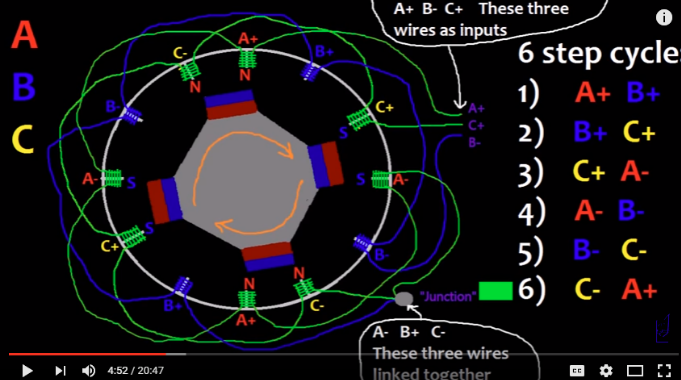
On further research I came across this video where they make a brushless DC motor inrunner, and this wiring diagram at 4:52 where four magnets and 12 copper coils are arranged in this manner. enter image description here enter image description here
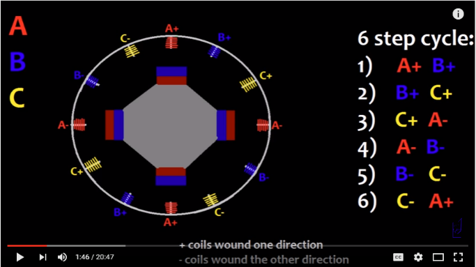
Is this the way it should be arranged? 8 magnets, 8 copper coils or 4 magnets 12 copper coils. For 8 magnets, 8 copper coils, what would be the possible copper coil wiring diagram for 3 phase or single phase output? Any suggestions?

\$\endgroup\$
1

1 Answer 1

1
\$\begingroup\$

The axial magnet motor is a terribly wasteful design; a magnetic path can be made short, and field leakage minimized, with iron pole parts (which they did not employ). For 3-phase current, you'll want to use a two-pole magnet disk (one N, one S) and three-pole pickup; each pickup will be connected as one winding of a WYE (and more important, each of the pickups will peak when the N magnet approaches it, and trough when the S magnet approaches it...). Six pickups and four magnets will work, too, if you wire it correctly.

The eight poles in the illustration all align at the same time over the eight coils, it won't generate more than two phases (from two possible magnet pole orientations) that way.

If the magnets were mounted on a steel disk, the flux from the side opposite the coils will return in the rotating metal disk. For most flux through the coils, a steel pole in the center of each coil, and a steel base under the coils, is recommended.

\$\endgroup\$
2
  • \$\begingroup\$ In this paper, they use coreless coils for reducing the cogging torque. I would like to go for a similar design with less weight by not using steel disk or steel poles. For a two pole magnet disk and three pole pickup, could you show an illustration of the winding as I am pretty much in the learning phases of electromagnetism. This would help me understand better. \$\endgroup\$ Commented Jul 30, 2016 at 16:24
  • \$\begingroup\$ The beauty of having three coils in the system, is... one wire of each coil connects to the WYE common (ground), and it doesn't matter which wire. The other ends of the windings will have three independent phases, that's your output. \$\endgroup\$
    – Whit3rd
    Commented Jul 31, 2016 at 5:15

Your Answer

By clicking “Post Your Answer”, you agree to our terms of service and acknowledge you have read our privacy policy.

Not the answer you're looking for? Browse other questions tagged or ask your own question.