0
\$\begingroup\$

I have built a case containing a Raspberry pi which controls a bunch of 12V based devices (using a relay board).

I am using a PSX3-C12AFC model power supply that takes my mains and drops it to 12V.

As per someone else's advice here, I have opted to use a simple car USB charger (for lighters) to go from 12v to 5v.

I would ideally like to have no power switch on the system at all: I plug it in the mains, and it starts up the Raspberry pi.

However, I'm concerned that the surge from either PSU (or combination of both) is not healthy for the raspberry pi. So far, I've been connecting the PSU and manually connecting the USB cable to the pi to avoid any funky business.

I'm looking to automate this with some form of circuit/device that would only give current to the Pi after the current has properly established.

I am not an EE, and can do moderate DIY stuff. Can anyone point me to the right resources to achieve this? Or even what the circuit I'm looking for is called?

Thanks.

\$\endgroup\$
6
  • 1
    \$\begingroup\$ Are you saying that you connect the output of the transformer directly to the input of the charger? \$\endgroup\$ Commented Sep 21, 2016 at 13:04
  • \$\begingroup\$ Yes, the transformer has a DC line-out of 12V. To that I connect (among other things) the car charger (like this). And to that I connect the raspberry pi (via USB cable). \$\endgroup\$
    – MB.
    Commented Sep 21, 2016 at 13:13
  • \$\begingroup\$ Oh, I see, you said "transformer" so I assumed you only had a transformer. What you have there is a power supply. \$\endgroup\$ Commented Sep 21, 2016 at 13:14
  • \$\begingroup\$ Ah, sorry for the vagueness. I have corrected the title. \$\endgroup\$
    – MB.
    Commented Sep 21, 2016 at 13:15
  • \$\begingroup\$ Have you measured a switch-on surge at the output of the 5 V adapter? Note that if you are powering the RPi through the USB connector, there may be inbuilt overvoltage protection - but you will have to check for your particular model of RPi. \$\endgroup\$ Commented Sep 21, 2016 at 13:18

2 Answers 2

1
\$\begingroup\$

Your PS3X-C12AFC 12v supply is a FAR more stable source than a car battery. And its turn-on transient is well controlled. This moves attention down-stream to the USB charger, and R-Pi requirements and characteristics.
Any turn-on transient created by the USB charger should never over-volt your R-Pi. I would hope that a USB charger is properly designed to not over-volt (they would very soon get complaints of blown USB appliances). And the USB charger should also cope with zero-to-full current as you plug a device into it. That said, many clone-makers of these "chargers" make it a weak-link in your power-supply chain.
The turn-on sequence that you describe (plugging the USB + R-Pi into a previously powered-up PS3X-C12) seems to work for you. Leaving everything connected, and plugging the PS3X-C12 into the wall should work fine. A "power-good" circuit is not required.
By-the-way, it is impossible to monitor current before applying power.

\$\endgroup\$
0
\$\begingroup\$

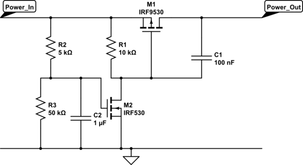
A quick and simple way of switching the power to the Pi on is simple enough.

schematic

simulate this circuit – Schematic created using CircuitLab

The turn on is controlled by C2 charging through R2/R3 until it hits the threshold voltage of M2. It's a little crude and may require a little playing with values depending on the exact parts used but it does give you a basic minimum voltage and time delay on the switch on.

When M2 turns on it pulls the gate of M1 low and turns on the power output to the Pi. C1 is optional and provides a soft start to the power output, it ramps the voltage up rather than switching as quickly as possible and risking pulling the input voltage down if the supply can't cope with the sudden change in demand.

Any low voltage N channel will work for M2, the threshold voltage of the part will determine the ratio needed for R2 and R3. The time delay after crossing the input threshold before turning on will determine the absolute values for R2,R3 and C2. M1 should have a threshold voltage of around -3V or less (assuming you're controlling the 5V rail) and be able to cope with the current draw of the Pi or whatever else it is controlling the power to.

If you can get the parts easily then replace M2, C2, R2 & R3 with a dedicated power on reset device. These are designed to hold a part in reset until a few milliseconds after the supply voltage has crossed a minimum voltage threshold. That would provide a cleaner way to drive the gate of M1.

Having said that you probably don't have anything to worry about, any in car USB adapter should be designed to cope with the mess that passes for a power supply in a car. It doesn't matter how nasty your 12V supply is, in comparison to a car it will be very low noise.

\$\endgroup\$
0

Your Answer

By clicking “Post Your Answer”, you agree to our terms of service and acknowledge you have read our privacy policy.

Not the answer you're looking for? Browse other questions tagged or ask your own question.