4
\$\begingroup\$

I have an audio-band piezoelectric transducer with a 17 kHz resonant frequency (among others). I'd like to use this transducer to acquire from an MCU an FSK modulated audio signal.

When I plug the transducer into the oscilloscope (with a 1 MOhms input impedance) and I observe the FFT of the voltage produced by the transducer, I observe a peak, with an amplitude of ~100 microvolts.

This amplitude is obviously too low for the ADC of the MCU, so I'd like to amplify the signal, but I don't have any idea how to do it.

How would you recommend to do that? For any purpose, transducer capacitance is supposed to be 13 nF at 120 Hz, according to the datasheet.

Thanks!

\$\endgroup\$
3
  • \$\begingroup\$ Look up audio microphone amplifiers. \$\endgroup\$
    – Andy aka
    Commented Oct 2, 2016 at 10:44
  • \$\begingroup\$ What's the FSK data rate? A 17Khz piezo resonance may be too narrow bandwidth to accept all the modulation sidebands of anything but very low data rates. \$\endgroup\$
    – glen_geek
    Commented Oct 2, 2016 at 18:41
  • \$\begingroup\$ With +/-200Hz deviation, 100 bauds symbol rate, I can easily decode the signal acquired by scope (thus with no amplification). Scope resolution is 0.3 mV. Goal of the project is to reach 200-300 bps. \$\endgroup\$
    – Vincz777
    Commented Oct 2, 2016 at 19:24

1 Answer 1

2
\$\begingroup\$

Those ceramic piezo transducers have an equivalent circuit very much like a crystal. The "13nF" spec (at 120 Hz) is a measure of Co. The piezoelectric properties translate mechanical flexing of the ceramic into mostly voltage, and a little current. Also introduced is Lm, Cm, Rm which are electrical equivalents of the mechanical motion. Lm and Cm is resonant at 17 Khz. Not shown are all the other resonant modes - each will have its own Lm, Cm, and Rm. (all in parallel). Although these motional components can be measured, its not easy and requires a test jig with measurement tools like function generator, oscilloscope.
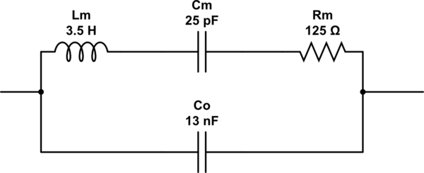
schematic

simulate this circuit – Schematic created using CircuitLab

Shown are some arbitrary component values for Lm,Cm,Rm. They are resonant at 17 Khz., but shouldn't be taken as accurate - many combinations of values are resonant at 17 Khz., one of which will model your transducer reasonably well.

This transducer will generate currents and voltages near 17 Khz. Source impedance varies over a huge range in a very narrow span of frequencies near 17 Khz. You could use almost any microphone preamp as a signal amplifier.
You can also use a high-impedance preamp to emphasize the parallel-resonance mode of the transducer. This preamp does two things: it amplifies voltage from a high-impedance source, and it presents to the Arduino a bias point about half-way between ground and Vref (assuming Vref=Vcc of 5v):
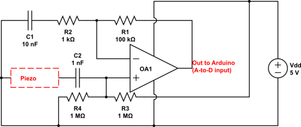
schematic

simulate this circuit This amplifier has a gain of almost 100 at 17 Khz., and gain can be reduced by replacing R1 with a smaller value. Be careful to choose a FET or CMOS op-amp for OA1 having a high gain-bandwidth product. It should also be a "rail-to-rail" op-amp having very low bias current. From Microchip, MCP631, MCP633 would work.

\$\endgroup\$
5
  • 1
    \$\begingroup\$ Thanks! I have a few questions, if I may: 1. How did you calculate Lm, Cm and Rm? 2. Co is 13 nF at 120 Hz, but what about Co at 17 kHz? 3. How do you choose the value of C1 and C2? 4. Is it possible to replace R3 and R4 by 10 MOhms resistors, as I'd like the circuit to be very low power? 5. Do you think the TI LPV511 would work, although its Gain - Bandwidth is only 27 kHz (again, looking for very low power)? Thanks a lot! \$\endgroup\$
    – Vincz777
    Commented Oct 2, 2016 at 17:38
  • 1
    \$\begingroup\$ 1)Lm,Cm can be found by comparing series resonance with parallel resonance. G3UUR shows a method.<br>pages.suddenlink.net/wa5bdu/crystal_slide_show.pdf<br> \$\endgroup\$
    – glen_geek
    Commented Oct 2, 2016 at 18:30
  • 1
    \$\begingroup\$ 2)Co is an actual capacitance between parallel plates of the piezo element, unlike Lm,Cm,Rm which are virtual.<br>3) C1,R2 form a high-pass filter, corner freq=16Khz. C2 hasn't a critical value<br>4)Bias currents of OA1 make it risky, but could be done.<br>5)No, GBW is too low, its noisy, bias I is high for R3,R4 of 10M \$\endgroup\$
    – glen_geek
    Commented Oct 2, 2016 at 18:36
  • \$\begingroup\$ Thanks a lot! Do you think I could find an op amp which would consume only a few uA? \$\endgroup\$
    – Vincz777
    Commented Oct 2, 2016 at 19:26
  • \$\begingroup\$ @Vincz777 - Look in Art of Electronics, 2nd Edition, the Low Power section for ideas, and I think, a list of particularly low-power op-amps. \$\endgroup\$ Commented Oct 28, 2021 at 15:45

Your Answer

By clicking “Post Your Answer”, you agree to our terms of service and acknowledge you have read our privacy policy.

Not the answer you're looking for? Browse other questions tagged or ask your own question.