3
\$\begingroup\$

I'm trying to built a circuit that amplifies music from a phone to a headset, based on ambient noise level. So if you're surrounded by noise, your music volume will turn up and in silent surroundings it will turn down.

My problem is that I want to implement a maximum where it stops turning up the volume no matter how much ambient noise there is, to avoid damaging the ears of the user. I think the max volume output (where the graph flattens out) should be in the range of 1-2V. I have included a figure to illustrate what I'm trying to do. I have looked into voltage regulators and I can see that it is quite simple for DC circuits, but not so much for AC circuits. Also, it would be easier to come up with a digital solution, but the learning goals for this semester limits me to work only with analog circuits... Any suggestions?

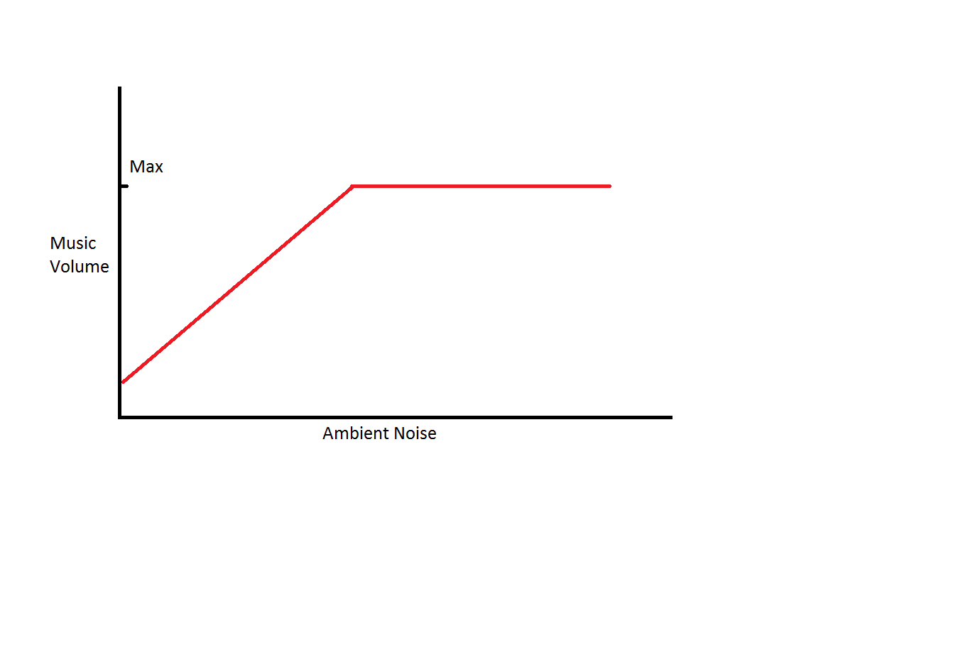
enter image description here

\$\endgroup\$
6
  • 4
    \$\begingroup\$ Get yourself a THAT2180 VCA, a microphone and and OP-amp and you should be good to go. \$\endgroup\$
    – winny
    Commented Nov 8, 2016 at 9:41
  • \$\begingroup\$ Thanks Winny! Unfortunately I don't have the expertise to fully understand that solution but I'll read up on it. Is the VCA somewhat the same as an Automatic Gain Control? \$\endgroup\$
    – ebon
    Commented Nov 9, 2016 at 12:46
  • \$\begingroup\$ Yes! If you find a good AGC and replace the auto part with your microphone + minor tweeks, you have your desired function. \$\endgroup\$
    – winny
    Commented Nov 9, 2016 at 15:13
  • \$\begingroup\$ Also, look for "audio compressor". \$\endgroup\$ Commented Nov 17, 2017 at 5:46
  • \$\begingroup\$ "My problem is" No, Sorry, but that's not your problem, Your first problem is distinguishing (and measuring) noise from music. If you can't do that, you can't increase the music level appropriately. And this is not a simple problem. \$\endgroup\$ Commented Apr 26, 2021 at 23:15

3 Answers 3

1
\$\begingroup\$

One of the things that come to mind is a device that an multiply 2 analog signals.

  • The first analog signal is your input audio signal

  • The second analog signal is a signal for the desired volume

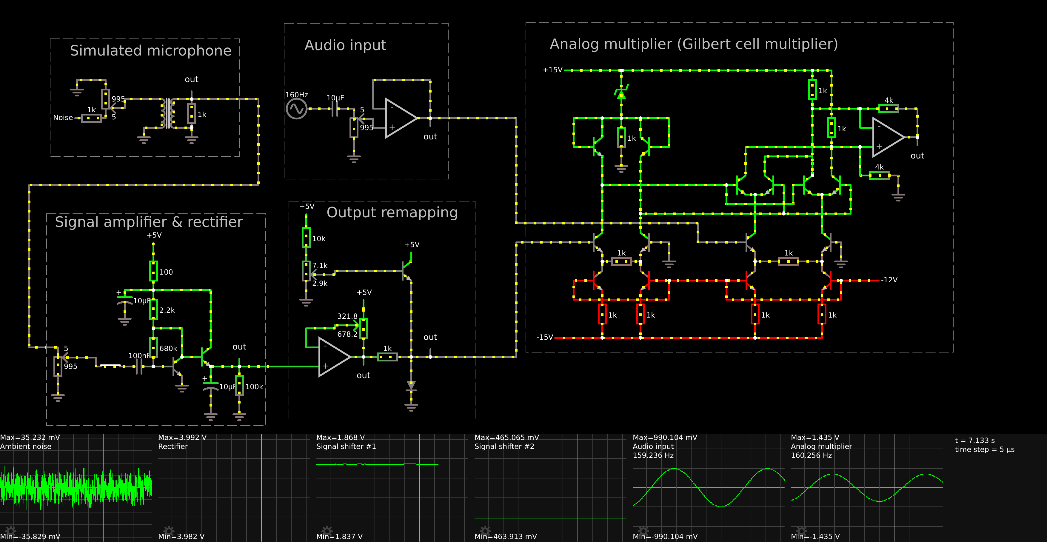
To get the desired volume signal, we amplify the signal from a microphone, then we rectify it. After rectifying, we low pass filter it to get rid of any peaks. We then level shift this signal to fix it for the next stages. This new signal then goes into an amplifier to reduce the impedance followed by a resistor and then a diode for clamping the signal. (or 2 diodes for stronger signal)

We now feed both signals into a analog signal multiplier like a Gilbert cell, which multiplies the volume control signal (0 to 1v) with our audio signal (-1 to 1v) to get the output we need.

Example of the modules for an circuit like this:

Circuit containing a simulated microphone, amplifier, rectifier & gilbert cell mixer

Open circuit in browser

\$\endgroup\$
0
\$\begingroup\$

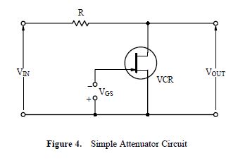
You have a very good idea there. A way to to what you want is to build an amplifier that has the maximum gain you want. Then feed it with this jfet attenuator; JFET antenuator

The maximum volume is then limited by the maximum gain of the amplifier.

You can find more about this antennuator here; App Note for JFET as a Resistor

\$\endgroup\$
1
  • \$\begingroup\$ Thanks for the quick reply, it's really helpful! I think it's a good and simple solution, but I might have a problem because of the volume-button on the phone. If the user changes the volume on the phone, the input of the amplifier will change, which will also change the output, regardless of the maximum gain. It will allow the max output volume to be higher than I want if the user chooses to turn up the volume on the phone. What I really want is a max output volume, that can never be exceeded no matter how much ambient noise there is and how much the user has turned up the volume on the phone \$\endgroup\$
    – ebon
    Commented Nov 9, 2016 at 12:38
0
\$\begingroup\$

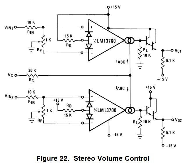
On page 14 of the LM13700 datasheet is this low-distortion stereo voltage controlled amplifier:

enter image description here

\$V_{IN1}\$ and \$V_{IN2}\$ are your left and right input audio signals, the voltage at \$V_C\$ determines the gain. With \$V_C = -13V\$, the gain is lowest, and when \$V_C = +15V\$ gain will be highest.

The supplies don't have to be ±15V, this IC can operate down to ±5V.

It is current through \$R_C\$ that determines the actual gain, so you can choose any resistance appropriate to provide the gain you require at whatever maximum voltage your "ambient noise level" detector is able to apply at \$V_C\$.

$$ I_{RC} \approx \frac{V_C + V_{supply}}{R_C} $$

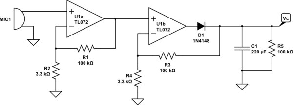
So you are left with the task of measuring ambient noise, and converting that into a voltage \$V_C\$. Something like this, perhaps:

schematic

simulate this circuit – Schematic created using CircuitLab

This is just a two stage microphone amplifier with a total gain of about 1000, and where the second stage doubles as a peak detector. C1 and R5 hold the output peaks from U1b, which decay at a rate of 50% over 10s or so. The output \$ V_C \$ is a suitable voltage to apply to \$ R_C \$ in the previous circuit, though \$ R_C \$ will cause the rate of decay to increase. If that's a problem, another buffer stage (voltage follower) may be in order.

\$\endgroup\$

Your Answer

By clicking “Post Your Answer”, you agree to our terms of service and acknowledge you have read our privacy policy.

Not the answer you're looking for? Browse other questions tagged or ask your own question.