0
\$\begingroup\$

I am trying to steer a 12v motor from my microcontroller's 5V pins (CHIP). I have successfully wired it up to support on and off which included an N-MOSFET, 100kResistor and a diode.

Now I want to be able to switch the motor direction also. I found this article: http://www.electronics-tutorials.ws/transistor/tran_7.html which claims that its possible with a N&P MOSFET. It includes this picture: enter image description here
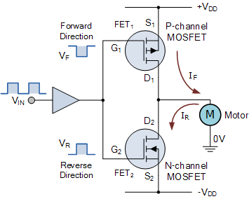
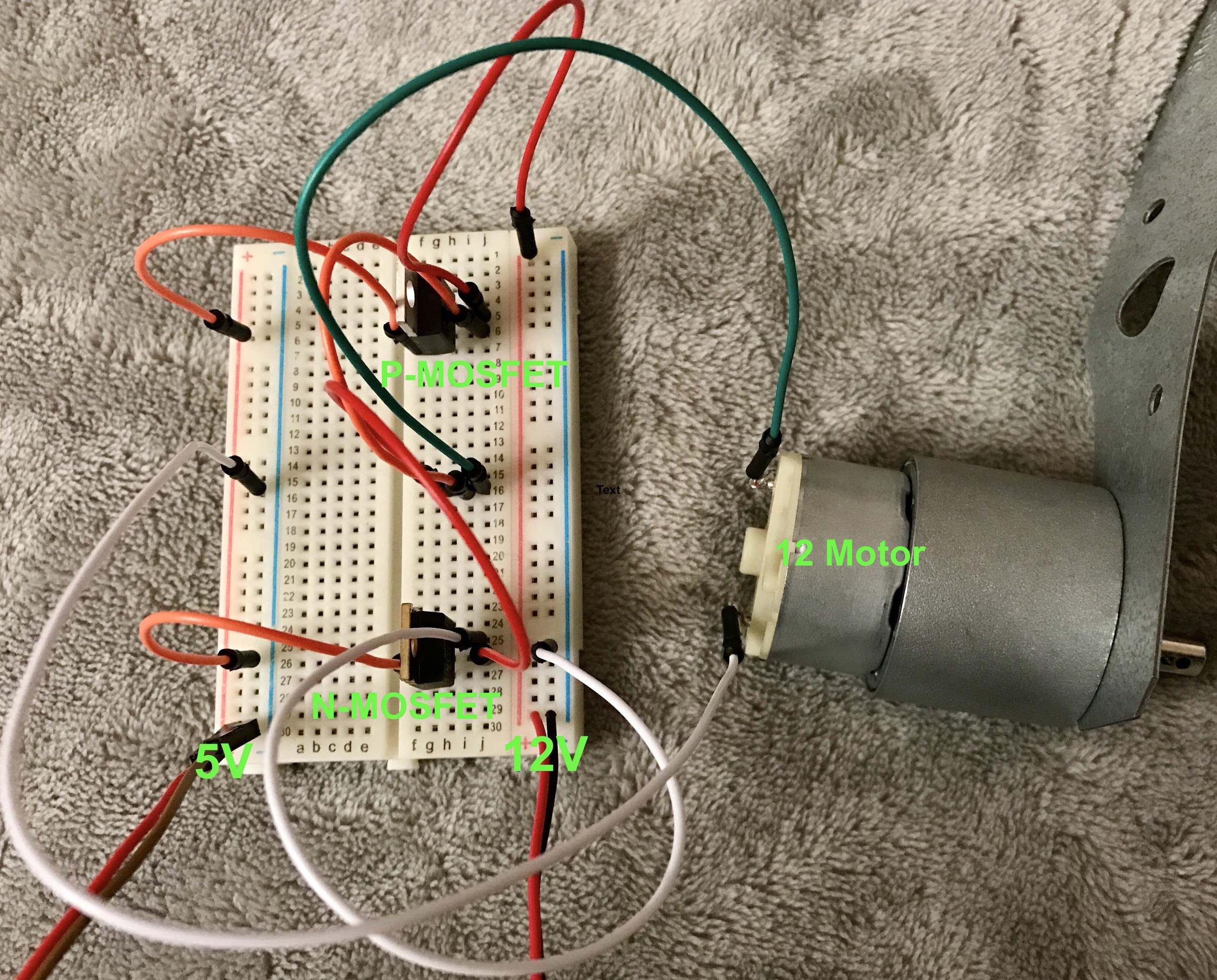
I have wired it up like this on my breadboard (the orange cables connecting to the gates i would manually move for now, later connected to two independent pins of a microcontroller): enter image description here But it doesn't work, moreover the N-Channel MOSFET gets really hot. 1) What's wrong in this setup? 2) Do I need to include any resistors or diodes, like i did in my simple example? 3) Am I correctly hooking up the 0V of the motor to the Ground of the 5v microcontroller (white cable)?
I'm still pretty new to electronics, so hopefully someone can help me out ;)

\$\endgroup\$
1
  • \$\begingroup\$ Have you done the math yet? Read the datasheets? \$\endgroup\$ Commented Nov 27, 2016 at 5:41

3 Answers 3

3
\$\begingroup\$

The cited article assumes that the control signal has the same full swing, from -VDD to +VDD. If VDD is 12V, the control signal of 5V in amplitude will not do the job. At some intermediate point both transistors will be open, and the entire 12V will be shorted by them, and transistors will be fried in no time.

To control a 12V motor in both directions, you should be using a H-bridge.

\$\endgroup\$
4
  • 1
    \$\begingroup\$ First, if the OP is using a single 12 volts supply (as I think he is), then he has not connected his circuit per the diagram. Second, if he uses + and - 12 volt supplies then his gate voltages will be +/- 24 volts when activated, which is outside the maximum gate voltage for most MOSFETs and will probably kill them. \$\endgroup\$ Commented Nov 27, 2016 at 6:24
  • \$\begingroup\$ @WhatRoughBeast, I don't think there is any point of discussing multitude of screwups in the "design". The OP is given a keyword, "H-bridge", and if he is not completely lost for electrical engineering as a software type, he should figure the H-bridge out on his own. \$\endgroup\$ Commented Nov 27, 2016 at 6:29
  • \$\begingroup\$ Thanks for your reply. Make sense! I was only using a single 12V supply. So an H-Bridge like sparkfun.com/products/315 or sparkfun.com/products/9479 seems to be fitted then, hm? \$\endgroup\$ Commented Nov 27, 2016 at 9:12
  • \$\begingroup\$ @BenMarten, yes, precisely, a H-bridge made by TI, or ROHM. It has all level-translation circuitry (TTL to bridge). And you can even control the motor RPM with pulse-width modulation. \$\endgroup\$ Commented Nov 27, 2016 at 19:20
2
\$\begingroup\$

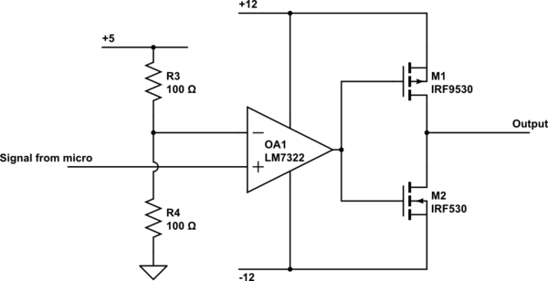
The driver for the circuit as shown cannot be a logic gate. To work in this configuration the FET gates would have to be driven by a rail-to-rail op amp such as the LM7322 configured as a comparator.

schematic

simulate this circuit – Schematic created using CircuitLab

While this will certainly work, and you can turn drive the motor with either a positive or negative voltage it has limitations if you only used a Pin output of 1=fwd 0=rev from the microprocessor.

To get speed control or to hold the motor stationary you would have to use a PWM signal. If the input is a square wave with equal high and low periods then the motor would be stationary. It will consume some power in this state (depending on the freq used) and if the switching frequency is in the audible range you will hear it (it acts somewhat like a speaker). As you change the duty cycle of the input waveform, the motor will move either fwd or reverse.

One last problem you need to think about with this type of drive circuit is that when you power up your microprocessor all the digital ports are likely to be set as inputs (essentially only with a pullup at best). This will mean that until you initialize your ports the motor will be driven. While the micro starts up and comes out of reset and you get to run your code could take mS. This might be enough to give the motor a sudden jolt at least.

If this is a concern you really need to have an enable/disable signal designed in.

\$\endgroup\$
2
\$\begingroup\$

First, you have to use a push-pull configuration such that N-CH MOSFET (or NPN BJT) transistor is on the top side and P-CH MOSFET (or PNP BJT) is at the bottom side. This is very important, else you will fry the transistor.

Then you can use a MOSFET gate driver IC, or use a buffer with discrete components, since this app. is not intended for fast switching.

But you will not be able to turn the motor CW/CCW without a positive and negative power source, what you really need is H-Bridge.

\$\endgroup\$

Your Answer

By clicking “Post Your Answer”, you agree to our terms of service and acknowledge you have read our privacy policy.

Not the answer you're looking for? Browse other questions tagged or ask your own question.