3
\$\begingroup\$

I am developing a project that consists of measuring the consumption of a power strip (not sure how it is in english/figure below). I'm already able to measure the instantaneous voltage using a voltage transformer. My next goal is to measure the current.
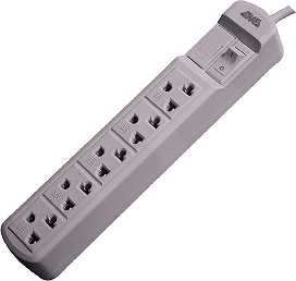
outlet

For this task, I found that I could use a current transformer with a high power burden resistor to reduce the current in proportion and generate a measurable voltage to be sampled in simple ADC [0V, 5V].

I got the transformer (figure below), but did not get any datasheet or information on how to use it. The only information I could decipher surfing the internet was that the "class" label indicates the error, which is, 1%.
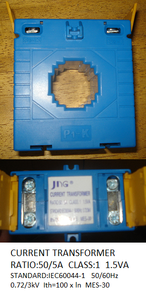
current-transformer

Where I live, the power grid works in 220V-RMS/60Hz. This current transformer serves for this purpose? What is the maximum current it can handle (assuming 220V-RMS)? What does it means the other informations? And above all, what does it means 1.5 VA? It is the maximum apparent power that it can handle?

The circuit I designed to interface between the ADC and CT is in the figure below. Consider that the current source is the CT, because the simulator that I used has no such component.
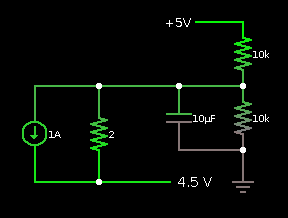
circuit

This schematic is correct?

Last question, should I put both wires (phase and neutral) in the current transformer, or only one of them?

\$\endgroup\$

2 Answers 2

3
\$\begingroup\$

Solution summary:

  • APPEARS likely to allow 6 ohms max across output with 3V max out at 50 A in.

  • Use 2W+ resistor

  • NEVER use with secondary open circuit.

  • Use only one wire of circuit through core (active or neutral OK).

  • Sensitivity can be increased by a factor of N by looping wire through core N times.


I almost agree with Mike with one important difference.
The transformer appears to be 50A to 5A rated or 50 A to 0.5A rated (see below) but with ANY resistor across the secondary up to 1.5 VA, which is 0.06 ohm. Voltage will then be V=IR = 5 x 0.06 = 0.3V as Mike says.

This seems very strange, as the turns ratio is far lower than usual and the output current much higher.

It seems more likely that the 1A/5A are certification currents and that the ratio is 100:1 as suggested by "Ith = 100 x In" on the label.

Then:
50A / 100 = 0.5A out at 50 A in Vout max = 1.5/I = 1.5/.5 = 3V
Power = I^2.R so R= P/i^2 = 1.5/.5^2 = 6R
Sanity check: I^2R=1/4 x 6 = 1.5VA.

Vmax allowed if the above is correct is 3V at 50 A. You can increase sensitivity by passing the same wire through the core several times. but you can not nominally produce more than 3V.

There are many references to this transformer on web but none seems to give additional information. eg here

\$\endgroup\$
2
  • \$\begingroup\$ I edited my answer to make that clearer! \$\endgroup\$
    – MikeJ-UK
    Commented Mar 7, 2012 at 16:59
  • \$\begingroup\$ Thank you for your answer! So, considering 100:1, I have to ensure that the voltage does not exceed 3 V (at 0.5 A), right? I will try to confirm the CT ratio with some experiments. \$\endgroup\$
    – borges
    Commented Mar 9, 2012 at 15:48
3
\$\begingroup\$

The ratio of 50/5A indicates that the transformer will give 5A secondary current with the rated current of 50A through the core and assumes that the secondary is shorted. The 1.5VA rating says that you can take up to 1.5VA of apparent power from the secondary without affecting the accuracy. This corresponds to a voltage of 0.3V across the secondary at 5A.

It sounds like you really need a voltage output proportional to the current which you will get with a higher resistance across the secondary (since the line frequency is constant) but this is not the normal mode of operation. The ratio of secondary voltage to primary current (the transimpedance) depends on the secondary inductance which isn't known but you could measure the output voltage with a range of known primary currents to determine this. If you get too little output, you could wrap the primary cable through the core several times to increase the sensitivity. I doubt that you will get much output with this transformer though since there are too few secondary turns.

You could try experimenting with a 12V toroidal mains transformer, passing one or two turns of your neutral line through the core and loading the original primary (now the secondary) with a resistor of a few k\$\Omega\$. This should give linear results as long as the current is sinusoidal.

And yes, you should pass only one wire through the core.

\$\endgroup\$
1
  • \$\begingroup\$ Thank you for your answer! I had two good answers, and unfortunately I can only accept one, but still I upvoted your answer. I'll do some testing and report them here later. \$\endgroup\$
    – borges
    Commented Mar 9, 2012 at 15:54

Your Answer

By clicking “Post Your Answer”, you agree to our terms of service and acknowledge you have read our privacy policy.

Not the answer you're looking for? Browse other questions tagged or ask your own question.