0
\$\begingroup\$

This may sound a weird question but couldnt resist to ask here.

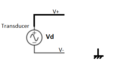
Lets say I have a differential signalling mode floating battery powered transducer(where the outputs are mirrored) and the differential voltage across its outputs Vd at a moment is 1V.

Lets call the output wire pairs as V+ and V-. At this moment I only know the differential voltage between V+ and V- by using a voltmeter or a scope as 1V.

Below illustrates the transducer and its differential outputs:

enter image description here

But in the above situation I dont know the voltage across V+ and the earth ground and similarly I dont know the voltage across V- and the earth ground.

Lets say I measure the voltage across the V+ and the earth and V- and the earth and I measure them as 101V and 100V respectively keeping the differential voltage as 1V again.

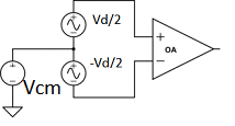
Imagine I hook up this transducer outputs to a differential amplifier where its system analog ground is earth grounded. I draw the equivalent circuit as:

enter image description here

In this case, the common mode voltage Vcm = (100 + 101)/2 = 100.5V

and

the differential voltage remains Vd = 1V

If it is true so far so good..

But in data-sheets of the amplifiers there is something called input common mode voltage range. I think it is the max voltage an amplifier can handle with respect its system ground.

And imagine this amplifier has +/-15V input common mode voltage range.

My questions are:

1-) Would the amplifier get damaged in this case?

2-) If it would, does that mean that I have to measure the differential output pairs of the transducer one by one with respect to system ground of the amplifier each time before I couple them? Is there a common practice for that?

\$\endgroup\$
12
  • \$\begingroup\$ What you have here is a system where your sensor is at +100 V ground level and your amplifier is at 0 V. Yes that would blow up that amplifier. What you're forgetting is that you cannot transport a differential signal using only 2 wires without re-defining the ground level (a transformer can do this). You also need the ground. So the sensor must also be at 0 V ground level or the amplifier must also be at +100 V CMM level. \$\endgroup\$ Commented Mar 5, 2017 at 16:30
  • \$\begingroup\$ Do you mean that in differential signalling, the transducer's GND must be connected to system ground of the differential amplifier? \$\endgroup\$
    – user1245
    Commented Mar 5, 2017 at 16:35
  • \$\begingroup\$ I think in my question without any common ground current cannot loop, was that your point? \$\endgroup\$
    – user1245
    Commented Mar 5, 2017 at 16:39
  • \$\begingroup\$ You said the common mode voltage was 100 V. When you say that you mean "relative to ground". And your "equivalent circuit" shows a Vcm source connected from ground, which provides a path for current to flow. \$\endgroup\$
    – The Photon
    Commented Mar 5, 2017 at 16:41
  • \$\begingroup\$ If you apply a 100 V common-mode voltage to an amplifier with 15 V maximum common mode input voltage, you will most likely blow up that amplifier. Why is that difficult to understand? \$\endgroup\$
    – The Photon
    Commented Mar 5, 2017 at 16:42

3 Answers 3

1
\$\begingroup\$

If you have a 'floating battery powered transducer', and you measure 100v between one of its outputs and ground, then you do not have a 'floating' battery powered transducer, you have a transducer which is for some reason 100v above ground.

If you connect that to an amplifier whose permissible common mode input voltage ranges +/-15v about ground, then it certainly would not work linearly, and it would probably get damaged.

If your transducer is truly floating, then it would take only a nominal resistor, say 100k, connected between ground and some terminal on the transducer, say one of the outputs, or a battery terminal, to bring it down to within the amplifier common mode voltage.

If your transducer is elevated to 100v above ground by, say, a connection to the system you are measuring, then you will have to use an amplifier with a larger common mode voltage input. Attenuating both outputs 10:1 with respect to ground will bring them both down to 10v, within your common mode range. You would need to take care to match the two attenuators very carefully, any mismatch will result in some common mode signal appearing incorrectly as differential.

\$\endgroup\$
4
  • \$\begingroup\$ But floating means it has no connection to system ground isnt it? Why not battery powered called floating source? I didnt get that point. \$\endgroup\$
    – user1245
    Commented Mar 5, 2017 at 16:57
  • \$\begingroup\$ @user, you're the one who said it was 100 V above ground, and presented a model showing that was caused by some 100 V source. A battery powered device with no connection to the ground of the amplifier circuit doesn't fit that model. \$\endgroup\$
    – The Photon
    Commented Mar 5, 2017 at 17:00
  • 1
    \$\begingroup\$ If it was truly floating, you'd measure near zero. As you've measured 100v, and not said 'but after I connected the meter it ramped down to 0v', implying it stayed at 100v, even into the load of the meter, then it's connected, somehow, to a 100v source. I've guessed it might be the system you're measuring, or it might be the battery charger, but only you can see what you've got there, as my 'all-seeing-eye' is not working too well at the moment. If you haven't measured 100v, then maybe it is floating, why lie to us and then get surprised when we get misled. \$\endgroup\$
    – Neil_UK
    Commented Mar 5, 2017 at 17:01
  • \$\begingroup\$ @ThePhoton Thanks. I will start more reading about it I think Im going very wrong directions. \$\endgroup\$
    – user1245
    Commented Mar 5, 2017 at 17:02
0
\$\begingroup\$

1) Not unless ESD event occurred which being CM insulated, makes it a susceptible target.

Otherwise floating battery powered Diff Amp works fine, then use optical or digital or magnetic isolation for output to data collection system.

The CM gain can be computed by the (series leakage to input shunt )resistance ratio * the tolerance error of the matched R's * differential gain. Coupling from Common Mode noise sources can be a problem if cables and R matching is not perfect as CM noise tends to be orders of magnitude large in E fields e.g. 10V/m from powerlines than the differential signal but also much higher impedance. So a CM shunt connection of grounds reduces this somewhat.

The environmental reasons for isolation depend on each application affect the solution. e.g. HV, safety leakage, RF immunity etc.

  • Sometimes a choke is used to get low f grounding but improved RF isolation.
  • Sometimes an RC connection is used for ground connections.

  • Sometimes an active CM signal is used to active guard the shield or use as a remote ground and only receiver ground connection is used for a shield. This is standardized as "Right Leg Drive" in patient monitoring.

\$\endgroup\$
0
\$\begingroup\$

The short answer is YES. If you have common mode voltages in excess of the Vcm range of an amplifier you will damage either the measurement system or the source sensor.

That said there are solutions to measurements in very high Vcm environments.
Amplifiers such as this optically isolated instrumentation amplifier or this capacitively isolated amplifier can stand off many kV.

\$\endgroup\$

Your Answer

By clicking “Post Your Answer”, you agree to our terms of service and acknowledge you have read our privacy policy.

Not the answer you're looking for? Browse other questions tagged or ask your own question.