0
\$\begingroup\$

I've been working on a project on my free time that requires a motor. I've been using a 6v motor (which has a positive and a negative wire). However, I found a mechanism in this bidet that I thought would be really useful for my project. I ripped it all apart, but I ran into a more complicated motor (12V, manufactured by Elensys, says "SP BN2A" and "16831" on top). This motor has five wires (red,black,orange,yellow,brownish).

I want to integrate it into my system, but I have no idea how to hook it up to my power. I've tried googling the documentation and nothing shows up, and trying all the possible wire combinations with a 9V battery to test whether it works (which I thought would be enough to make it move, albeit slowly).

How do I make it move and do what I want it to? If possible, could someone also explain how I could hook it up to my Raspberry Pi without frying it?

\$\endgroup\$
3
  • \$\begingroup\$ Some people can't even s...t without Raspberry Pi. \$\endgroup\$ Commented Jul 11, 2017 at 17:47
  • \$\begingroup\$ I was able to find this regarding your motor: tradekorea.com/product/detail/P683533/… You have a 2-2 phase excitation motor. Do some research on how to drive those and come back if you have questions. \$\endgroup\$
    – Chris M.
    Commented Jul 11, 2017 at 18:23
  • \$\begingroup\$ @Chris M. Ok so from what I understand, I need a micro controller, such as the HCS12 recommended by this website (www.nxp.com/docs/en/application-note/AN2974.pdf) or the PIC16F84 recommended by this website (imagesco.com/articles/picstepper/01.html). By how it looks, I'm guessing I would use it similiarly to how I use my L293D now. Is all of this correct? If so, I still have the question of how I would wire it up. Where would each of the 5 wires from my motor go, as well as the positive and negative wires? Thank you so much for your help! \$\endgroup\$
    – NeonCop
    Commented Jul 12, 2017 at 16:59

1 Answer 1

1
\$\begingroup\$

First, let's lay out the available specs for the motor for posterity:

  • 12VDC rated voltage
  • 2-2 Unipolar drive
  • 4-phase
  • 400Hz Max starting frequency
  • 1/64 Gear reduction ratio

2-2 phase excitation is commonly referred to as "full-step", and in this case, you're exciting two phases each time, as in Fig2:
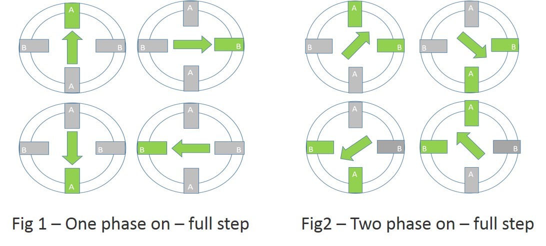
enter image description here

To make it move, you have to drive it with a stepper motor controller. Unipolar motors use coils that are center tapped, making four effective phase coils. These center-taps are often tied together internally, giving 5 leads as you have.

From here I was able to find a wire color code that uses the colors you have. As such, I believe it to be:

  • Yellow -> Coil 1
  • Brown -> Coil 2
  • Red -> Common
  • Orange -> Coil 3
  • Black -> Coil 4

"Common" in this case is not a common ground, but rather the center-taps of the two coils. Your motor V+ is supplied on this line (I'd probably try it at 10V or so to stay below the rated voltage).

The other 4 lines are for your pulse-train. Unfortunately, there's no available current spec for the motor. Considering that you already have the the L293D it seems reasonable to at least attempt to drive the motor with that before pursuing a higher-powered motor driver.

You would then wire up the L293D to the motor as shown in this tutorial, with the following connections between motor and driver:

  • Coil 1/yellow -> Pin 3
  • Coil 2/brown -> Pin 6
  • Coil 3/orange -> Pin 11
  • Coil 4/black -> Pin 14

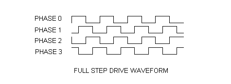
The respective input pins are 2, 7, 10, and 15. To those, you'll need to send pulse trains from your Pi in this manner:
enter image description here

With Phase 0 corresponding to Pin 2, Phase 1 to Pin 7, etc. Note that two phases are always "high" or "excited" at any given point in time, as we said above.

Pin 8 of the L293D should be connected to your Common line.

This should get you (hopefully) moving in the right direction.

I'm no expert on stepper driving, but this is how I understand it. If I've said anything egregiously wrong, please let me know and I'll fix it. I'm not above admitting and correcting mistakes.

\$\endgroup\$
6
  • \$\begingroup\$ I connected all the wires as indicated in your tutorial. However, I have two problems. First, the pin 8 which you suggested I should connect to the common line, is already connected pin 8 -> pin 16 -> positive side of the battery. Second (related to the first), I am unsure where to connect the negative side of the 9V battery to. I am bypassing the 5v Raspberry Pi current because I don't want to fry the Pi, but am unsure if I should connect it to the negative side of the breadboard, the ground pin, or somewhere else? \$\endgroup\$
    – NeonCop
    Commented Jul 12, 2017 at 23:01
  • \$\begingroup\$ The datasheet for the L293D says that Pin 16 is the internal logic Vcc, and is recommended to be between 4.5V and 7V (nominally 5V), while Pin 8 is the Vcc for the driver output and would be selected based on the motor you're driving. You can feed both 5V if you're running a 6V motor, but not for 12V (well, you can, but there's a decent chance the motor won't have enough to turn). The negative side of the battery gets grounded to one of the ground pins (4, 5, 12, or 13), all of which should be grounded together to prevent ground loops. \$\endgroup\$
    – Chris M.
    Commented Jul 12, 2017 at 23:38
  • \$\begingroup\$ Does this schematic make sense? Or will it destroy my Pi? Thanks so much for your help! \$\endgroup\$
    – NeonCop
    Commented Jul 13, 2017 at 17:51
  • \$\begingroup\$ Based on the L293D sheet, you should be okay with that setup. The enable and A pin current draw is well below what the Pi can provide. One thing I noticed is the use of 9V at both Pin 8 (output Vcc) and Pin 16 (logic Vcc). It's not going to hurt the L293D, as it's rated for up to 36V on both of those, but as I said, it's recommended to put ~5V to pin 16. If it was me, I'd put the 5V line from your power supply (on the left, I assume) onto the breadboard, and then run one line to Pin 16 of the L293D and another to the 5V Pi pin. \$\endgroup\$
    – Chris M.
    Commented Jul 13, 2017 at 18:26
  • \$\begingroup\$ Ok, so I hooked up the internal power to the Pi, the battery's power to both the 'motor driver pin' in the IC and to the Common line in my motor, grounded all the IC ground pins and the negative side of the battery. The 4 coils are each connected to an IC Output pin, and their corresponding input pins are connected (in the order you said) to pins 26, 19, 6, and 24. WHile this makes the motor vibrate when I input this code, the motor is still not owrking. Are there any other things it could be? \$\endgroup\$
    – NeonCop
    Commented Jul 13, 2017 at 22:24

Your Answer

By clicking “Post Your Answer”, you agree to our terms of service and acknowledge you have read our privacy policy.

Not the answer you're looking for? Browse other questions tagged or ask your own question.