6
\$\begingroup\$

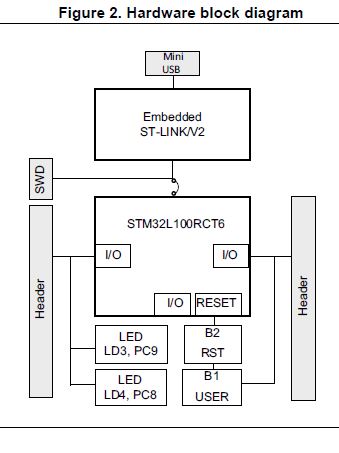
I am using STM32L1 Series Discovery board and want to do uART communication via same UART port that is Used for Embedded ST Link V2

enter image description here .

Embedded ST Link uses USART1 of STM32L100CT6 and Mini USB is connected to my PC. Refer following fig.

PA9 Pin  as USART1_Tx of STM31L100CT6
PA10 Pin as USART1_Rx of STM31L100CT6

I also connected JP1 that is provided on the board so now main problem with this is that I didn't find COM port !!!

Is it possible to use ST Link USB for UART Communication ?

\$\endgroup\$
2
  • \$\begingroup\$ "So is it possible to use ST Link USB for UART Communication ?" - Nope. \$\endgroup\$
    – JimmyB
    Commented Jul 31, 2017 at 9:02
  • 1
    \$\begingroup\$ The STM boards that support the arm mbed system do just this so it is in theory possible with the correct drivers installed on the PC. Whether the st-link firmware on that specific board supports it or not is another matter. \$\endgroup\$
    – Andrew
    Commented Jul 31, 2017 at 10:36

4 Answers 4

1
\$\begingroup\$

No, it isn't possible (without a hardware modification, and custom ST-Link firmware). PA9 and PA10 are connected to the LCD display and the side headers, but not connected in any way to the onboard ST-Link.

You can however do that with a Nucleo board, where PA2 and PA3 (USART2) of the target controller are connected to the onboard USB controller, but of course it doesn't have that nice LCD display.

\$\endgroup\$
2
  • \$\begingroup\$ this is not true, stlink supports serial communication with host via usart, and most boards provide it. since you have what, 6 uart peripherals. mine on discovery is uart 3. \$\endgroup\$ Commented Apr 15, 2020 at 20:05
  • \$\begingroup\$ @AntonStafeyev Yes, but some of the low-cost ST-Link adapters don't route it out to the connector. In such cases, it will need a modification. \$\endgroup\$
    – user148298
    Commented Mar 20, 2023 at 13:52
2
\$\begingroup\$

If what you really need is a "serial terminal" you can convert the ST link to J-Link and use Segger RTT. It works like a serial terminal, but over JTAG.

\$\endgroup\$
0
1
\$\begingroup\$

It needs stllinl 2.1 to work. And it needs the user tx rx pins being routed out.

More details here. https://dannyelectronics.wordpress.com/2016/05/01/uart-debugging-over-st-link-v2-1/

\$\endgroup\$
0
\$\begingroup\$

If you have an ST-LINK V2 clone and are willing to make a minor hardware modification and sacrifice a 5V output rail, serial debugging is definitely doable as either UART or SWO.

Disconnect the trace leading to the 5V pin, which isolates it from the power rail by scraping a small channel across it with a sharp pin or blade. Next, solder a bodge wire from pin PA1O on the MCU to the now disconnected 5V rail. A resistor from 22V to 100V can be added for protection, but may not be necessary. Pay careful attention to the pins arrangements. They often differ even between two nearly identical-looking boards.

The following two links detail the hardware modification: https://lujji.github.io/blog/stlink-clone-trace/ https://www.youtube.com/watch?v=JqrUAzjJ0tw

\$\endgroup\$

Your Answer

By clicking “Post Your Answer”, you agree to our terms of service and acknowledge you have read our privacy policy.

Not the answer you're looking for? Browse other questions tagged or ask your own question.