2
\$\begingroup\$

After extensive research and finding very helpful circuits for the rest of the system I still have not found what im looking for. I am building a PoE raspberry pi weather station that will be mounted on a 30 meter tower so access is limited.

The challenge is as follows. The AC source is unreliable so I have a +-2 hour battery backup inside the weather station. The idea is to monitor the AC input, battery voltage, and Pi state ( Shutdown or not). When the AC is not avialable the Pi will run off the battery. when the battery nears depletion the circuit must send a signal to the PI which will run shutdown script.

When the AC supply is restored the "Run" pins on the Pi needs to be toggled to reboot the pi. the issue is the reset circuit cannot just reset the pi every time the AC comes back and falls away. becuase if the run command is given to the PI While still running on battery it has a good chance of corrupting the SD card. my current solution is a Arduino pro micro programmed to check all the conditions and only reset the PI when the Arduino it self sent the shutdown command.

Is there a way todo all of this with simple circuit ?

\$\endgroup\$
5
  • 3
    \$\begingroup\$ Are you just asking for a "brown-out" circuit? \$\endgroup\$
    – jonk
    Commented Aug 1, 2017 at 4:49
  • 2
    \$\begingroup\$ I'm thinking you need 3 things: 1) A comparator that tells you the AC mains is gone, 2) A comparator that tells you your battery voltage is low, 3) A pair of edge-triggered D-flip flops. In the Rpi, you run SW that senses when AC is gone AND your battery is low. If true then it drives an IO high to trigger a flip-flop to tell it Rpi will need a reset. Then you run shutdown command on Rpi. Now that the flip-flip is activated, the next time AC comes back, it holds the Pi RESET line low for say a second. Does that sounds right? Let me know and I'll post an answer. \$\endgroup\$ Commented Aug 2, 2017 at 16:04
  • \$\begingroup\$ That sounds correct in principle yes, just remember the circuit is 5v logic and pi can only handle 3.3v on GPIO's \$\endgroup\$
    – Rustie0125
    Commented Aug 3, 2017 at 4:44
  • 2
    \$\begingroup\$ The problem statement seems to be mistaken. You don't need to "reset" the pi, rather you need to disconnect it from the battery supply, and only reconnect it to the AC mains after those have been stable for a credible amount of time and the battery has charged enough that it will be able to sustain operation of the pi for the amount of time required to cleanly shut it down again, should the AC mains almost immediately fail. \$\endgroup\$ Commented Dec 30, 2017 at 5:34
  • \$\begingroup\$ Even simpler: mount SD read only and avoid corruption. Pi has such settings. If you need an sd for logging, add one over usb. Having an external power cycler is probably good to have too just in case it locks up or something, but not needed for preventing sd corruption. You also don't need anything fancier than some diodes and caps to 'switch' between battery and AC (powering the DC rail) \$\endgroup\$
    – Abel
    Commented Feb 10 at 13:07

3 Answers 3

1
\$\begingroup\$

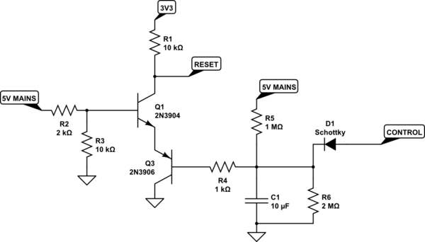
Is your charging circuit wired this way? With the PI ADC monitoring the battery voltage at the red circle?

enter image description here


schematic

simulate this circuit – Schematic created using CircuitLab

When the PI is powered (CONTROL pin is high) & 5V mains is powered; 3V3 supply is still available. The Reset pin will pull high to 3V3 via 10k ohm; Q1 is close and Q3 is open.

When the PI is powered (CONTROL pin is high) & 5V supply is gone; 3V3 supply is still available. The Reset pin will pull high to 3V3 via 10k ohm; both Q1 and Q3 is open.

When the PI is powered (CONTROL pin is high) & 5V supply is gone and return back; 3V3 supply is still available. The Reset pin will pull high to 3V3 via 10k ohm; Q1 is close and Q3 is open.

When the PI is shut down (CONTROL pin is input / float) & 5V supply is gone and return back; 3V3 supply is still available. The Reset pin will go low then high again; Q1 is close and Q3 is close momentarily then high. To change the timing of the toggle, adjust C1 cap.

Note: Please test out circuit on breadboard. Also do test the condition when you don't have Mains and your battery is totally flat.

\$\endgroup\$
14
  • \$\begingroup\$ Thank you for the feedback, where does the battery condition come into play ? \$\endgroup\$
    – Rustie0125
    Commented Aug 1, 2017 at 8:08
  • \$\begingroup\$ When the MCU detect a low voltage and you send a command to shutdown, set your "Control" pin as input. In other normal working conditions; both mains and battery power, it should set as output high. \$\endgroup\$
    – Jason Han
    Commented Aug 1, 2017 at 8:22
  • \$\begingroup\$ Are you refereeing to the Pi or the Arduino as MCU ? the purpose of the questions is to get rid of the arduino all together \$\endgroup\$
    – Rustie0125
    Commented Aug 1, 2017 at 9:21
  • \$\begingroup\$ My bad. Use the fruit to send a 5V signal to control this circuit and it should work without the MCU (Arduino). \$\endgroup\$
    – Jason Han
    Commented Aug 1, 2017 at 9:28
  • \$\begingroup\$ Hope my alteration makes sense \$\endgroup\$
    – Rustie0125
    Commented Aug 2, 2017 at 4:16
1
\$\begingroup\$

If that weather station software is written in a portable way (Python?), it could be actually easier to port it on a board which has proper battery support. Then you could simply configure shutdown on low battery in OS settings, and the only thing you would need to implement in hardware is a reset signal as rising_edge(PSU_OK) AND not(CPU_RUNNING) which can be done with a couple of BJTs and an RC timing circuit to detect the edge. Single-board computers with battery support also typically stop draining the battery when you switch them off, which is not the case of the RPi.

If you want to stick with using the RPi, using an Arduino for power management is not a bad idea at all. It will let you change all your parameters (battery voltage threshold, shundown/reset timings) easily, which won't be the case if you implement this in hardware.

One should also bear in mind that the RPi also needs you to supply a battery charging circuit with overcharge and over-discharge protection (but you probably know that already).

\$\endgroup\$
0
\$\begingroup\$

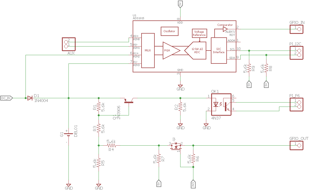
So Taking your Idea and applying it. will look something like this. enter image description here

The Battery is boosted to 5v before this circuit and the Pi can not handle more then 3.3v so a ADC in inserted. The pi requires a signal to be pulled to ground to reset the pi. if my understanding is correct. the circuit will work as follows. when the Pi is shutdown the output pin to the transistor will be low allowing the DC applied signal to be sent to the optocoupler and reset the pi. once the pi boots a script will write the transistor base HIGH stopping the dc signal from reaching the opto unless the pi is shutdown. at the same time when the pi is running on battery the pi can check battery voltage and shut the pi down when battery goes flat. Once the DC input is restored the same logic applies as explained above.... correct ?

\$\endgroup\$
3
  • \$\begingroup\$ PS i Know the resistor values are wrong. \$\endgroup\$
    – Rustie0125
    Commented Aug 1, 2017 at 12:28
  • \$\begingroup\$ It's a simple logic circuit and I think an ADC will not be needed. Let me re-draw another one for you. \$\endgroup\$
    – Jason Han
    Commented Aug 2, 2017 at 4:39
  • \$\begingroup\$ Yes your drawing is correct \$\endgroup\$
    – Rustie0125
    Commented Aug 2, 2017 at 6:09

Your Answer

By clicking “Post Your Answer”, you agree to our terms of service and acknowledge you have read our privacy policy.

Not the answer you're looking for? Browse other questions tagged or ask your own question.