0
\$\begingroup\$

For a transfer function, a zero is defined as the value of s for which the transfer function's value is zero. A pole is defined as the value of s for which transfer function's value goes to infinity.

However when dealing with transfer function for an amplifier, a zero depending on right hand or left hand may decrease or increase phase, introduces +20 db/decade in gain and similarly for a pole (left hand for stability), decreases the phase response and introduces -20 db/decade in gain.

What's the significance of the definition of pole and zero for an amplifier's frequency response? Is it not valid?

\$\endgroup\$
3
  • 2
    \$\begingroup\$ What you're asking is not clear. Poles and zeros affect gain and phase angle in the frequency response. Zeros may be anywhere in the s-plane; closed loop poles must be in the left half plane for a stable system (an open loop pole may be in the right half plane as it can often be compensated by a zero). \$\endgroup\$
    – Chu
    Commented Sep 16, 2017 at 7:59
  • \$\begingroup\$ You seem to grasp what poles and zeroes are so please try and ask a clearer question. \$\endgroup\$
    – Andy aka
    Commented Sep 16, 2017 at 12:30
  • \$\begingroup\$ Because an amplifier A(s) contributes to the loop gain A(s) beta(s) as much as the feedback network does. \$\endgroup\$
    – sstobbe
    Commented Sep 16, 2017 at 17:33

3 Answers 3

1
\$\begingroup\$

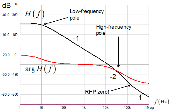
Why would it be different for the frequency response of an amplifier or a power converter? If I take the following transfer function \$H(s)=H_0\frac{(1-\frac{s}{\omega_{z1}})(1+\frac{s}{\omega_{z2}})}{(1+\frac{s}{\omega_{p1}})(1+\frac{s}{\omega_{p2}})}\$ which is the transfer function of a boost converter operated in the discontinuous conduction mode (DCM), the frequency response is below:

enter image description here

You can clearly see a gain in dc (\$H_0\$) then the effect of the poles and zeros. You realize the action of the right-half-plane zero (RHPZ) which brakes the -2 slope (-40 dB/dec) into a -1 slope (-20 dB/dec) but keeps lagging the phase at high frequency.

\$\endgroup\$
1
\$\begingroup\$

I may be a bit off here, but I think you are trying to find out where the definition for pole/zero match with the 20dB/dec and phase shift.

The answer is actually that the position of the pole heavily influences the transfer function. Poles can be anywhere on the complex plane. And if you get close to those poles (on the complex plane), then you will indeed see that you will get to infinity there.

However, a bode plot, transfer function or anything similar doesn't cover that whole complex plane. It will stay on the imaginary axis! And so unless your poles are exactly on the imaginary axis, you won't see any point going to infinity.

The following figure illustrates this with the transfer function:

\$TF(s)=\frac{1}{1+s+s^2}\$
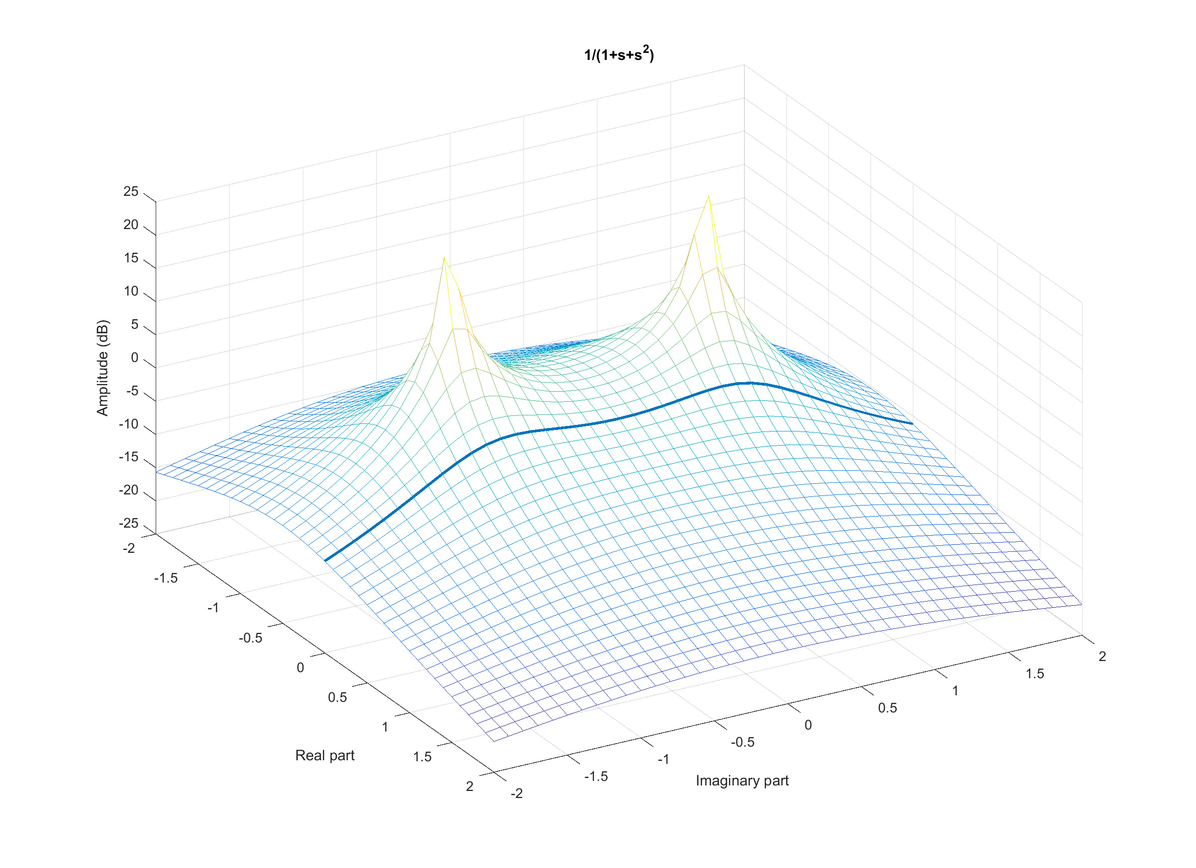
Amplitude in dB of 1/(1+s+s^2) in the complex plane

The bold line is the frequency axis that you use for bode plots or transfer functions. But you see that it "misses" the poles completely.

What is possible though, is to describe behavior far away from the poles when going along the frequency axis. Let's take a simple transfer function 1/(1+s) and follow it along the frequency axis:

\$\left|\frac{1}{1+j\omega}\right|=\frac{1}{\sqrt{1+\omega^2}}\$

If \$\omega\$ becomes much larger than the pole frequency, then

\$\frac{1}{\sqrt{1+\omega^2}} \overset{\omega\rightarrow +\infty}{\approx} \frac{1}{\omega}\$

If \$\omega\$ is multiplied by 10, then the amplitude will decrease by a factor of 10, which is 20dB, and so you get -20dB/decade. You can make the same approximation for the phase of the transfer function. A Left-Half Plane pole will add 90 degrees phase shift as you increase \$\omega\$ beyond the pole frequency.

The same reasoning applies to LHP zeros (eg. \$TF(s)=1+s\$), where you will see that, as \$\omega\$ increases, similar things happen to the amplitude and phase, albeit in another direction (+20dB/decade rather than -20dB/decade, and -90 degrees rather than +90 degrees).

Doing the same analysis for RHP poles and zeros will lead to the same conclusions for the amplitude, but they lead to inverted phase shifts.

\$\endgroup\$
0
\$\begingroup\$

Maybe that would help you:

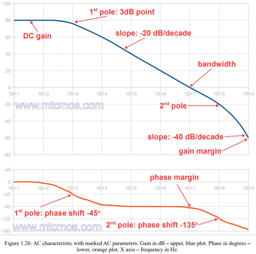
AC characteristic of an opamp

Source: https://payhip.com/b/5Srt

\$\endgroup\$

Your Answer

By clicking “Post Your Answer”, you agree to our terms of service and acknowledge you have read our privacy policy.

Not the answer you're looking for? Browse other questions tagged or ask your own question.