1
\$\begingroup\$

I have acquired an Elliott Progress No.1 pillar drill with a Crompton Parkinson motor. It must date from the 1960s. The motor worked fine when I first acquired it. The rest of the drill was in a bad state, so I stripped and restored it and gave the motor a good clean. It's single phase with two windings, a centrifugal start switch, and a start capacitor. Once reassembled, I wired it back up the way it was when I dismantled it, and switched it on. The motor emitted a loud buzzing sound but did not move.

The bearings are good, there are no obstructions, and the spindle turns smoothly by hand. One thing I did notice was that with the power on the spindle locked – I couldn’t turn it in either direction until I cut the power.

I've spent weeks trying to get it to work, and have scoured the web for ideas. I found a few posts on various forums that described similar motors, but none quite the same. I've run out of options and hope someone with more knowledge may be able to help me. I'll describe the configuration as clearly as I can.

There are notches for six terminals on the connection plate inside the motor marked, from top to bottom, K, Z, AZ, S, A, T. K and S are empty.

  • Mains live was connected to T, neutral to A, earth to the earth terminal. A wire runs from T to what I believe is an overload switch, and from the switch to AZ.
  • From AZ, one wire runs to the centrifugal switch. On the other side of the switch a wire runs into one of the windings. Another wire runs from AZ into another of the windings.
  • Apart from mains neutral, two wires were connected to A, one running to a capacitor, the other into one of the windings.
  • The other side of the capacitor was connected to Z. Another wire led from Z to one of the windings.

I’ve tested the resistance of the windings, one is quite high (around 19 ohms), the other much lower (around 4 ohms). I presume the first is the start winding, the second the run winding.

The centrifugal switch seems ok, no missing, damaged or corroded parts or obstructions.

I replaced the original start capacitor with one of the same specification, but this makes no difference.

I’m 99.9% sure this is exactly how it was wired when I dismantled it for cleaning. I can’t work out what the problem is. Although my electrical knowledge is basic, I got the impression that the start capacitor is supposed to be placed before the centrifugal switch in the circuit to provide the start winding with additional torque. As it is, it seems to be placed between the two neutral terminals, A and Z. Much Googling later, I am none the wiser as to why this should be.

How do I get this motor working again?

UPDATE: one of the winding wires snapped while I was working on the motor and I lost the end. It's now beyond recovery unless I replace the windings, which I suspect would cost more than a new motor. Thanks everyone who helped!

\$\endgroup\$

3 Answers 3

2
\$\begingroup\$

One thing I did notice was that with the power on the spindle locked – I couldn’t turn it in either direction until I cut the power.

One possible problem is that the rotor is moving axially. If you removed the rotor, you may have made an error in reassembly. There were probably several washers of different types at each end. In addition, the centrifugal switch must engage with a mechanism on the shaft. There may be something not right about those items either because of a reassembly error or a mechanical failure.

I can't think of a wiring error that would make the shaft lock.

\$\endgroup\$
4
  • \$\begingroup\$ There were no washers on the spindle; when assembled the rotor is secured by the bearings in the end bells and I can detect no axial play in the spindle. The switch does engage with a weighted and spring loaded collar on the spindle - this appears to be functioning properly. \$\endgroup\$
    – Bird
    Commented Nov 27, 2017 at 23:35
  • \$\begingroup\$ Is there any possibility that the two end-bells have been interchanged or the stator body turned end of end? \$\endgroup\$
    – user80875
    Commented Nov 27, 2017 at 23:47
  • \$\begingroup\$ No, the motor spindle fits through a hole in one bell, the other doesn't have a hole. The stator must be the right way round because the connections to the windings are at one end - the switch contact board in the end bell can only attach to that end of the stator. \$\endgroup\$
    – Bird
    Commented Nov 28, 2017 at 10:24
  • \$\begingroup\$ If the rotor is truly locked, not just hard to turn, with power applied, it must be either jammed against the stator or not centered in the stator and being jammed against one end. For the rotor to be jammed against the stator only when energized, the bearings would have to be loose. If the rotor is not centered in the stator, it would be pulled toward the center when the motor is energized and thus jammed against one end. Could the rotor or stator have shifted with respect to the shaft or housing? If the motor fails to self-start, it should turn if given a strong enough manual twist. \$\endgroup\$
    – user80875
    Commented Nov 28, 2017 at 11:29
0
\$\begingroup\$

The centrifugal switch contacts must be CLOSED when the motor is at rest. The description of what it's doing sounds as though the Start winding is not energized. The Run winding has no relative phase rotation, so it just vibrates a little back and forth, what you perceive as being locked up.

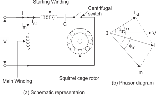
Most likely you installed the centrifugal switch backward and the contacts are OPEN when at rest, so no power is getting to the Start winding and the cap is not in the circuit. Here is a wiring diagram of a Capacitor Start single phase motor. Note that in this, and most diagrams available on the Internet, the centrifugal switch is shown in the OPEN position, leading people to think that's how it is supposed to be wired, but it's kind of a mistake in the depictions. That switch is only open AFTER the motor gets to about 80% speed. enter image description here

\$\endgroup\$
3
  • \$\begingroup\$ I did think that might be the problem, but I've checked this very carefully and established that the switch is indeed closed when the motor is at rest, and current is running across it. \$\endgroup\$
    – Bird
    Commented Nov 27, 2017 at 23:13
  • \$\begingroup\$ Does it hum loudly when on? Does it freely turn when Off? 6x normal current A to AZ is the starter winding much lower DCR than the run coil Z to ZT \$\endgroup\$
    – D.A.S.
    Commented Nov 27, 2017 at 23:15
  • \$\begingroup\$ Yes to both of the first questions, humming and turning. I'm not sure about the DCR - is that DC resistance? My understanding is that it's an AC motor. One winding has much higher resistance than the other (see original post); I think the higher resistance winding is the start coil (thinner wire). \$\endgroup\$
    – Bird
    Commented Nov 27, 2017 at 23:28
0
\$\begingroup\$

The wiring resistance seems different to this site... (* different model) yet similar.

Z to T resistance =10.2 ohms A to AZ resistance = 7.4 ohms When wired up for forward rotation the resistance between the Live and Neutral wires is 4.2 ohms

http://www.instructables.com/id/Dismantling-a-Brook-Crompton-AC-motor-from-a-Myfo/

I believe the speed switch goes to AZ. This is just the DC resistance or DCR and this impedance determines the start current but the current drops back EMF cancelling the applied voltage as the speed rises.

Check your windings. A to AZ must be the switched winding to produce >5x start current. If this motor does not turn and does not hum then the Line to neutral resistance is wrong which should be less than the A to AZ since it is in parallel with the run windings Z to ZT

\$\endgroup\$
3
  • \$\begingroup\$ I found the page in the link some time ago. The motor looks almost identical to mine. However, the author says his motor doesn't have a start capacitor, and his pictures show that there is no overload switch in the end bell (although space for one, and holes for the mounting screws, are clearly visible at the bottom). The wiring he describes is subsequently slightly different. Could it be that my motor shouldn't have a capacitor? \$\endgroup\$
    – Bird
    Commented Nov 28, 2017 at 10:19
  • \$\begingroup\$ you didn't answer my query about hum(on), friction(off) and DCR on line to neutral (ohms) \$\endgroup\$
    – D.A.S.
    Commented Nov 28, 2017 at 18:49
  • \$\begingroup\$ Did you not receive it? I answered it yesterday; it's showing on my thread. The motor hummed loudly and the rotor turns freely when the power is off. Although it's academic now as unfortunately the start winding is kaput (see update in my original post). Thanks for your help, though. \$\endgroup\$
    – Bird
    Commented Nov 28, 2017 at 19:57

Your Answer

By clicking “Post Your Answer”, you agree to our terms of service and acknowledge you have read our privacy policy.

Not the answer you're looking for? Browse other questions tagged or ask your own question.