2
\$\begingroup\$

I'm having a hard time designing a PCB for a sensor array that need to detect if there is a small reflective object (3-20 mm section) in the way. That object can slowly rotate around a shaft.

I have tested several sensors,sharp GP2Y0A21YK0F, EE-SY410, HSDL-9100-021... and all have some zones where my uC is unable to detect if there is an object or not because most of the light is reflected. I still have to test opb9000 (not done yet because of the communication protocol) and vl530x (TOF sensor), but I expect to get similar results.

With the custom PCB i have used discreet emitter/receivers. The emitter is optoisolated with a small barrier. There is some crosstalk but I can detect in most of the cases if there is a key with a decent threshold. I'm able to do analog measurements and filter it on software, buy I prefer to make my life easier and pulse the IR emitter at 10 kHz, make an analog narrow bandpass filter and recover the signal without the DC component, induced noise and amplified to the full range of my ADC.

Now the questions: Someone can recommend me a cost/effective layout to detect the object without adding sensors in a different plane? I know that there is some math and optics involved to get it exactly right but some layout ideas might help. I can pulse up to four IR emitters independently.

Shall I try a different sensing method? I think that the bandpass is quite nice method to improve noise immunity at low cost.

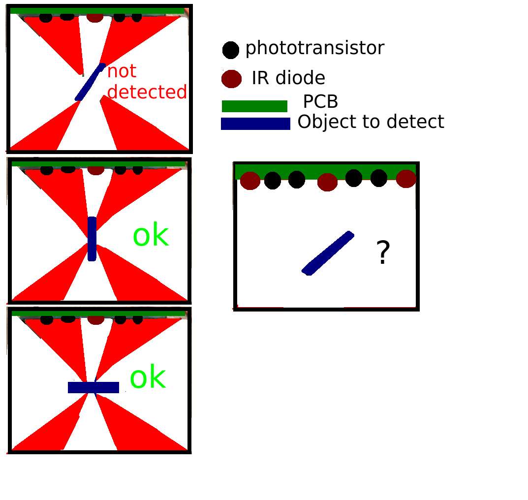
Image to help to understand the question. When the small side of the object is in the red area the sensor fails to determine if the object is in there. (The measurement is too close or the same that the one without the object)enter image description here
\$\endgroup\$
4
  • \$\begingroup\$ You should experiment with a wider position of the outer receivers. There is no theoretical answer to this based on the data you have provided. \$\endgroup\$
    – Andy aka
    Commented May 30, 2018 at 11:28
  • \$\begingroup\$ If you can change the shape of the object you use a radar detector shape: use a cross. \$\endgroup\$
    – Oldfart
    Commented May 30, 2018 at 11:53
  • \$\begingroup\$ How does this work in the second picture, is there any reflective surface on the other side? the small side is reflective? \$\endgroup\$
    – Dorian
    Commented May 31, 2018 at 18:57
  • \$\begingroup\$ I have tested the vl53L0X and works good enough for my application, so I will use it because is more convenient. I think that what @Andyaka said make sense and i will like to try it if i had more time. I can't change the shape Oldfart. Dorian both sides are reflective, and both are detected when they are perpendicular to the emmiter. I have all the receivers in parallel. I think that have them connected to a different pins and reading them one by one might help. What about have several emitters as in the drawing of the right? A more even light might help with the detection. \$\endgroup\$ Commented Jun 4, 2018 at 14:03

1 Answer 1

0
\$\begingroup\$

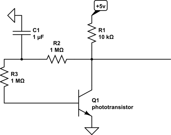
Consider an adaptive-phototransistor detector.

schematic

simulate this circuit – Schematic created using CircuitLab

\$\endgroup\$
1
  • \$\begingroup\$ Thank you for your answer. Interesting circuit but I can't use this method because the base is not accessible on the package that i'm using. There is the link to the datasheet in the first post. \$\endgroup\$ Commented Jun 4, 2018 at 14:03

Your Answer

By clicking “Post Your Answer”, you agree to our terms of service and acknowledge you have read our privacy policy.

Not the answer you're looking for? Browse other questions tagged or ask your own question.