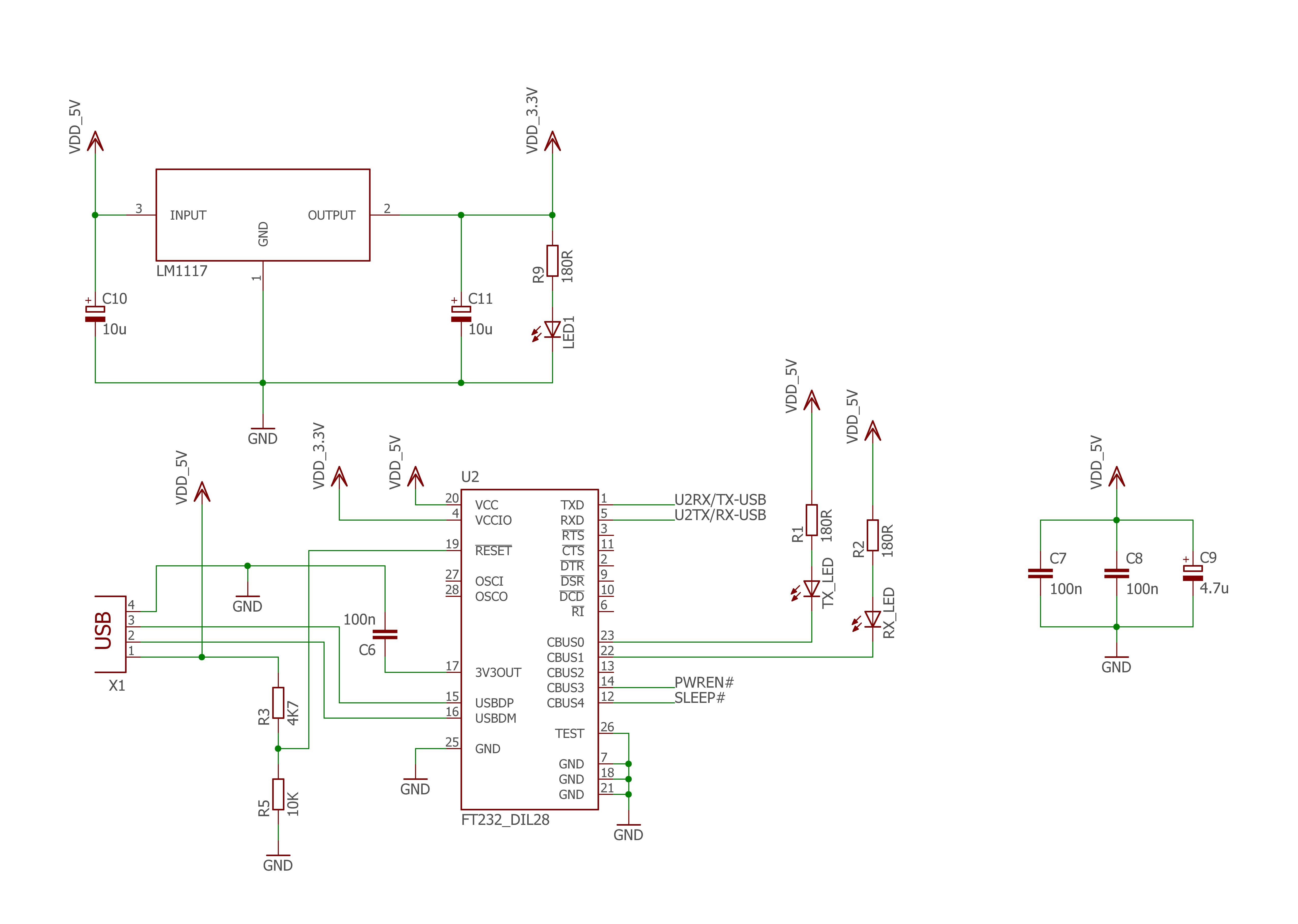
I'm planning to use the FT232R in my USB device. The device consists of the FT232R and a dsPIC33EP64MC202 (Basically speaking, the FT232 and a microcontroller only).
On the FT232R's datasheet, at the end of page 26, section 6.4, it talks about another possible configuration, using an LDO voltage regulator, which would be supplied by the 5V of the USB bus. This LDO can be used to supply between +1.8V and +2.8V to the VCCIO pin and to the external logic.
So, I have some doubts:
- Why does the LDO regulator voltage need to supply 1.8V to 2.8V? I made this question because we can connect the 3.3V pin to VCCIO either, and the 3.3V pin has 3.3V, no?
- I'm planning to make PWREN# and SLEEP# available to be used by my microcontroller to verify and decide when and how to enter in low power mode. Is there a problem in doing this?
- The voltage source that drives the TX_LED and the RX_LED is the 5V from USB bus, and not the 3.3V from LDO, correct?
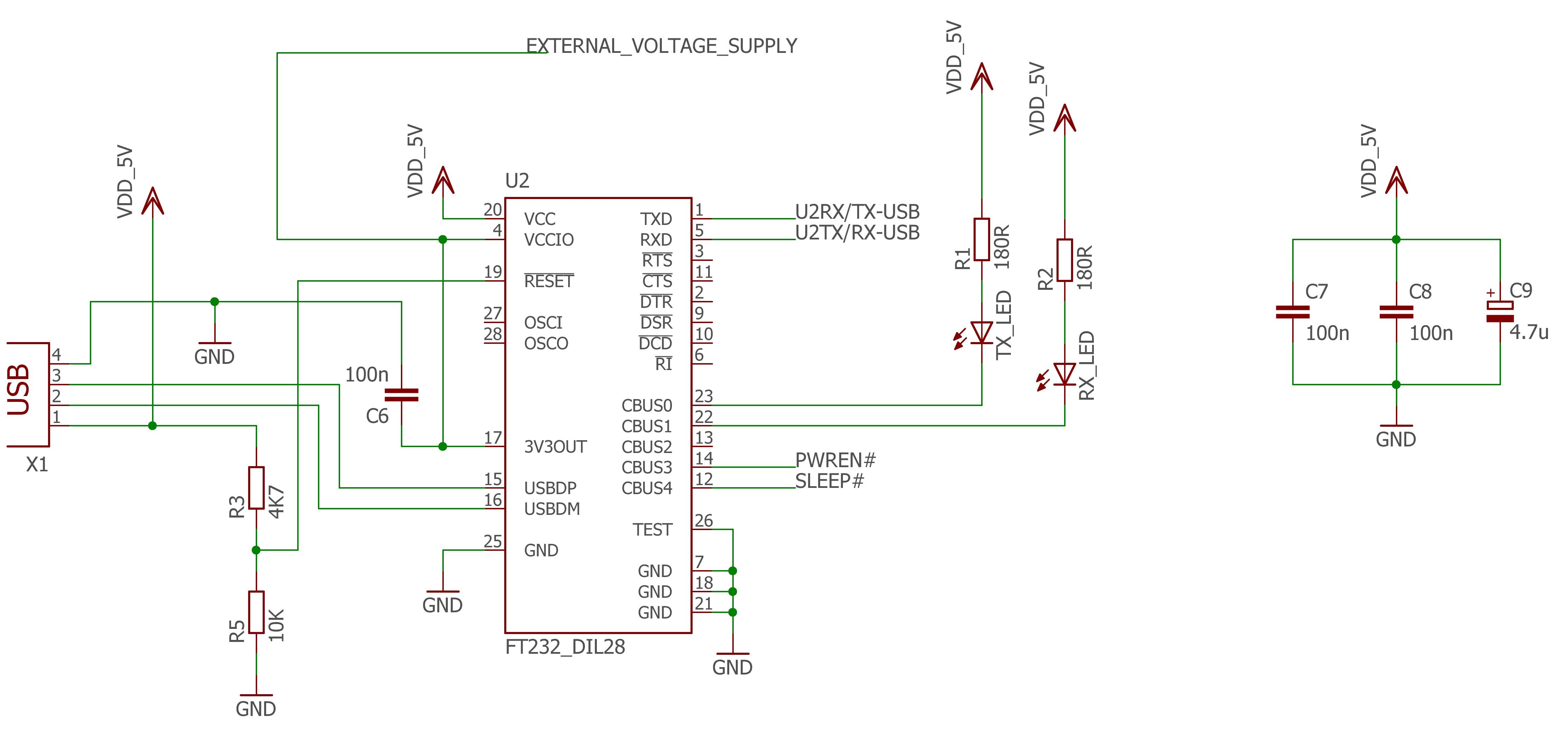
Here is another version. In the next picture, the VCCIO pin and the external voltage supply are supplied by the 3.3V pin from the FT232.
I'm not planning to make my microcontroller follow the Low Power mode protocol, at least not for now. But, configured this way showed in the second image, the FT232 can interrupt the current to my microcontroller. Am I right?
What do you think about these schematics, I'm afraid to have some electrical mistake, because the device will need to be available on a server to be accessed by other people.
Any help would be very appreciated.
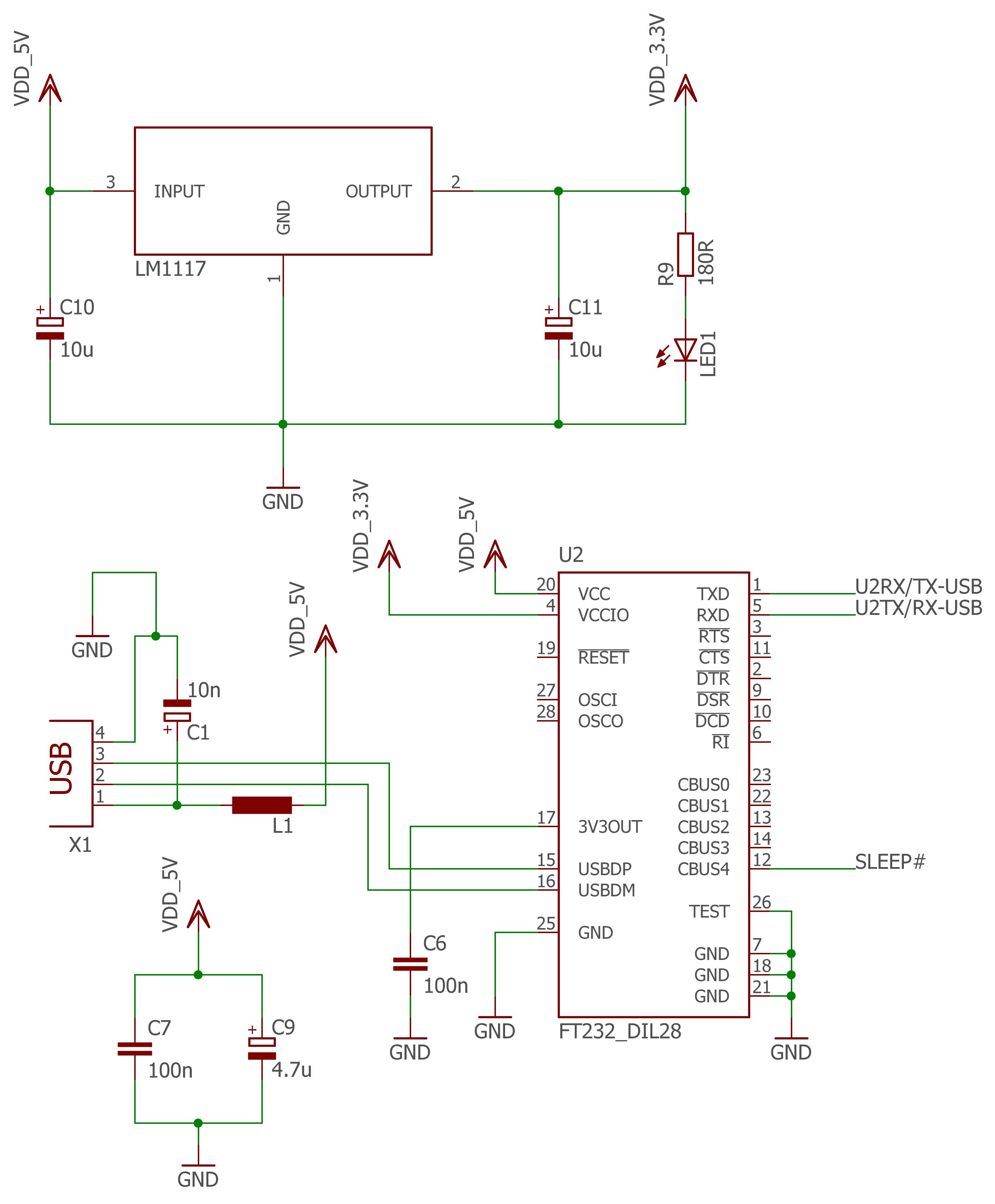
From tips and alerts made by Maple, I made some corrections, I came to this solution:
The LEDs RX_LED and TX_LED are not necessary, so I took them out


