0
\$\begingroup\$

The question is in bold at the bottom, the following is background.

I am going to measure air flow with a hot wire anemometer using the FS7 sensor from Innovative Sensor Technology (IST). They provide an application note for the sensor linked below.

https://www.ist-ag.com/sites/default/files/AFFS7_E.pdf

The application note includes a wheatstone bridge circuit to use with the sensor on page 11. The schematic is recreated below.
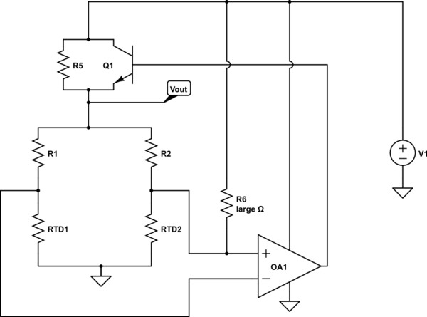
schematic

simulate this circuit – Schematic created using CircuitLab

I believe I understand the operation of the circuit, excluding R5 and R6.

One idea is that R5 is there for startup. If the circuit turns on and both amplifier inputs are at 0 volts, the bridge is balanced, Q1 stays off, and nothing happens. R5 ensures that current flows through the bridge so that the amplifier inputs move away from 0V and then the op amp can balance the bridge.

A guess is that R6 is for startup too, ensuring that the non-inverting input has some positive voltage to turn on the transistor and start current through the bridge. I don't see why it is necessary if R5 does the same thing.

What is the purpose of R5 and R6? If they are for startup, are they both necessary?

\$\endgroup\$
0

3 Answers 3

0
\$\begingroup\$

This is a MAF (mass air flow) measuring circuit. It works by maintaining a constant temperature difference between the two RTD elements, using one of them as a heater.

The thermal path between the two elements is cooled by the air flowing across it, and the power required to maintain the ΔT is a nonlinear function of the mass flow rate.

The values of R1 and R2 are selected to unbalance the bridge by just enough to establish the desired ΔT. R5 provides the initial startup current, and any additional current through Q1 is used to compensate for cooling by air flow.

R6 is simply there to reduce the loop gain for better stability (as the application note you linked to explains). Its value depends on the exact opamp used.

\$\endgroup\$
4
  • \$\begingroup\$ Thanks for your answer. If I understand your explanation of R6 correctly, that it decreases the amount of positive feedback, it could just as easily be connected to ground, replaced by a capacitor, or replaced by a capacitor in parallel with R1. Would you agree? \$\endgroup\$
    – DavidG25
    Commented Jun 21, 2018 at 17:28
  • \$\begingroup\$ No, not without a considerable amount of additional analysis. \$\endgroup\$
    – Dave Tweed
    Commented Jun 21, 2018 at 17:39
  • \$\begingroup\$ Then I am not sure I understand. If the role of R6 is to decrease the amount of positive feedback, why could it not be connected to ground rather than the power supply with identical results? Both the power supply and ground are AC grounds. \$\endgroup\$
    – DavidG25
    Commented Jun 21, 2018 at 17:58
  • \$\begingroup\$ Yes, but this is essentially a DC circuit. In particular, the phase shift introduced by a capacitor could be problematic. I'm not interested in doing that analysis, so I can't agree to your suggestions. \$\endgroup\$
    – Dave Tweed
    Commented Jun 21, 2018 at 18:23
0
\$\begingroup\$

You are correct in that R5 is there for start-up. R5 gives the bridge and op-amp a symmetrical bias to work with. R6 gives the op-amp a asymmetrical offset, but a tiny one, for stability reasons.

It is implied and necessary that R5 have a value outside the operating range of Q1. It is implied and necessary that R6 be in the meg-ohms, far above the values used in the bridge.

A quote from the application guide:

The R6 resistor is placed for stability of the anemometer circuit. Depending on used operational amplifier, it should be valued from 1.1 MΩ to 3 MΩ

Once the loop is active and Q1 controls the current, R5 has no effect, at least not above the accuracy levels the design engineer wanted.

This also allows for extreme ranges of RTD1 and RTD2, such that if both were to have a very low resistance, then Q1 might cut off, but R5 and R6 ensure that cannot happen.

The bridge could be more accurate without R5 and R6 injecting tiny offset currents, but at the risk of lock-up if the bridge goes beyond tracking range of the op-amp.

\$\endgroup\$
5
  • \$\begingroup\$ Is it necessary to have symmetrical bias and an asymmetrical offset? It seems to me either one would be sufficient on its own to start the circuit. \$\endgroup\$
    – DavidG25
    Commented Jun 20, 2018 at 21:45
  • \$\begingroup\$ @DavidG25. Not my design. I am a minimalist, so I would go with R5 or R6 but not both. \$\endgroup\$
    – user105652
    Commented Jun 20, 2018 at 21:47
  • 1
    \$\begingroup\$ You really should read the application note before answering. As it explains, R6 is not for "start up", but rather to reduce the loop gain to improve the stability of the circuit. \$\endgroup\$
    – Dave Tweed
    Commented Jun 21, 2018 at 0:26
  • \$\begingroup\$ If R6 is for stability, doesn't that imply that it's not for startup? \$\endgroup\$ Commented Jun 22, 2018 at 14:08
  • \$\begingroup\$ @ScottSeidman. I have corrected that snafu. Thanks for spotting it. \$\endgroup\$
    – user105652
    Commented Jun 22, 2018 at 18:33
-2
\$\begingroup\$

Interesting circuit. I'll have a stab.

First, the opamp is going to do whatever it has to to try to keep its inputs at the same potential. The only way it has of doing this is by turning Q1 more on or off. What this in turn does is changes the DC current flowing in the bridge, because Q1 shunts R5.

As DC current increases, the potential on both inputs will rise, because the voltage across R5/Q1 decreases.

As this happens, the very small standing current through R6 decreases. Let's say that the balance of the bridge is otherwise unaffected; this means that the tendency of R6 to make the + input more positive than the - is reduced. Therefore the output goes negative, turning off Q1. There is negative feedback, tending to stabilise the bridge.

\$\endgroup\$
4
  • \$\begingroup\$ "As DC current increases, the potential on both inputs will drop, because the voltage across R5/Q1 has to increase." This is obviously wrong. If the total current increases, then \$V_o\$ must rise because of the resistive network between it and ground. Therefore, the voltage across R5/Q1 must drop, not rise. In other words, Q1's current increases faster than R5's current decreases. \$\endgroup\$
    – Dave Tweed
    Commented Jun 21, 2018 at 0:16
  • \$\begingroup\$ yes, correct - I got it the wrong way around. oh well ;-) \$\endgroup\$
    – danmcb
    Commented Jun 22, 2018 at 3:57
  • \$\begingroup\$ You should either edit or delete your answer. \$\endgroup\$
    – Dave Tweed
    Commented Jun 22, 2018 at 12:43
  • \$\begingroup\$ The OP asked what are R5 and R6 used for?. Where is your answer to that question? \$\endgroup\$
    – user105652
    Commented Jun 22, 2018 at 18:38

Your Answer

By clicking “Post Your Answer”, you agree to our terms of service and acknowledge you have read our privacy policy.

Not the answer you're looking for? Browse other questions tagged or ask your own question.