0
\$\begingroup\$

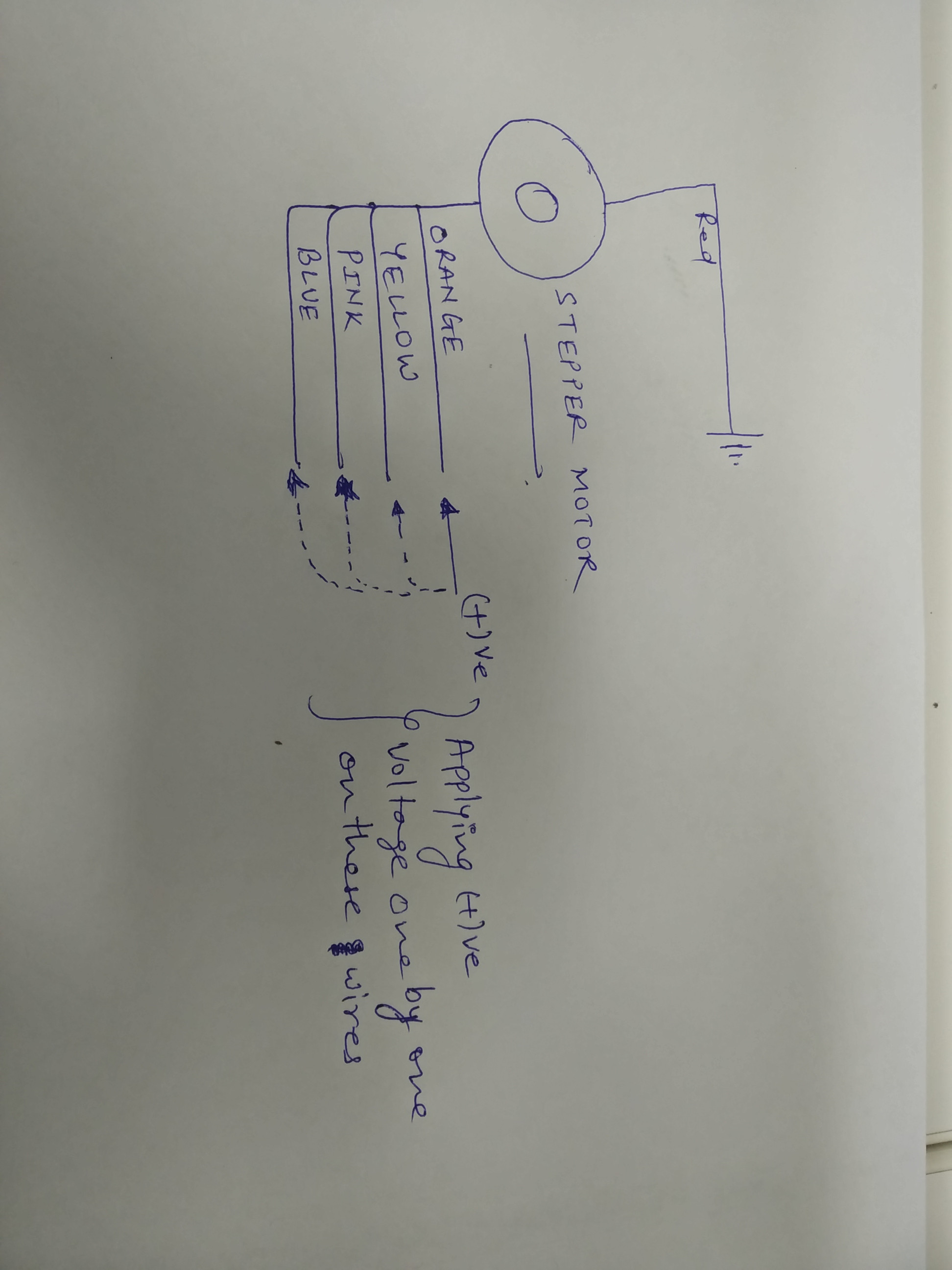
enter image description hereI am trying to test a 12V stepper motor using just a 12V DC adapter without any driver, but I am unable to get it triggered. I am using Velleman's MOTS1 motor and as per the data sheet attaching the power's negative terminal to the red wire and the positive terminal one by one to the other four wires.

1). To eliminate the possibility of a faulty motor, I even tried with two different motors of the same model. But both motors did not work.

2). I also realized that the adapter is delivering 11.8V instead of exact 12V. So, to eliminate the possibility of lower voltage, I supplied 15V using batteries, but that too did not work.

3). Also, using the same adapter and battery sets, I am able to trigger other regular 12V DC motors.

So most probably, I am doing something wrong here specific to stepper motors.

Please help! Let me know if you need more information from me.

I am an absolute newbie electronics hobbyist and have just 3 months of basic theory and practical experience. So, I guess, every suggestion is helpful :) .

Motors specifications from the Velleman's website - https://www.vellemanusa.com/products/view/?id=351245&country=us&lang=enu

  • resistance: 280 ohm
  • rated voltage: 12 Vdc
  • current: 32 mA
  • impedance: 380 ohm
  • phase: 4
  • step angle / step: 5.625° / 64
  • reduction ratio: 1/64
  • detent torque: 4.86 ozf.in
  • pull-in torque: 4.17 ozf.in
  • max. starting pulse rate: 550 pps
  • max. slewing pulse rate: 90 pps
  • temperature range: 77 °F
  • noise: 40 dB
  • cable: 420 mm AWG 1095#28
  • terminal: JST SPH-002T-P0.5S
  • insulation strength: AC 600 V - 1 sec. cut-off current: 10 mA
  • colors:
    1. B1: pink
    2. A1: orange
    3. A2: yellow
    4. B2: blue
    5. GND: red
    6. GND2 (for MOTS2): brown

DC Adapter specifications:

  • DC Volt Output: 12V
  • DC Current: 2.5 A
\$\endgroup\$
3

4 Answers 4

0
\$\begingroup\$

Driving a stepper motor is a bit more complicated than driving a regular brushed DC motor. Stepper motors require a stepper controller to energize the phases in a timely sequence to make the motor turn. I strongly recommend you build yourself a driver for this motor.

All the best, keep well.

\$\endgroup\$
2
  • 1
    \$\begingroup\$ Thanks for the reply! Sure, will go ahead in sometime and build a driver for running it, thats my ultimate intention. But since building the driver is a bit complicated, I thought to test the motor initially manually and thats where I got stuck. I am feeling that if I am not able to see it moving in small angles by applying manual power in the correct sequence, then I might run into the same problem with the driver circuit too. Is my understanding correct? \$\endgroup\$
    – Anurag
    Commented Jun 25, 2018 at 18:42
  • \$\begingroup\$ STTY's post is incorrect, to the limited degree that it is an answer at all. You can in fact drive a stepper by manually sequencing the coils, though for high steps/revolution it becomes boring rather quickly. Do note the question starts off by explaining that the goal is to test the motor, not to operate it. \$\endgroup\$ Commented Jun 26, 2018 at 6:48
0
\$\begingroup\$

You can test your motor(s) by simply applying voltage (below 12V is also acceptable) and seeing a small movement only. For further spin test requires more advanced driver circuitry.

Looking at the reference page, your motor looks like a 5-wire unipolar motor.

5-Wire Motor This style is common in smaller unipolar motors. All of the common coil wires are tied together internally abd brought out as a 5th wire. This motor can only be driven as a unipolar motor.

(Refer to: https://learn.adafruit.com/all-about-stepper-motors/types-of-steppers)

Simply tie GND pin to ground and apply positive voltage to A1, A2, B1 and B2 pins one-by-one.

What a simple stepper driver does is applying sequential pulses to the windings. This application manual is very explanatory for beginners.

\$\endgroup\$
5
  • \$\begingroup\$ Hey pacman - Thanks for the detailed reply! Yes, I will construct a driver circuit when actually using this motor. Regarding the steps you mentioned for testing it manually, I am actually following the exact same steps, but for some reason, the motor is not moving at all. I followed the following sequences - A1, A2, B1 B2; A1, B1, A2, B2; B1, A1, A2, B2. No luck :( . Could it be that the current being drawn through the adapter is less than 32mA? But I used 15V battery too through which certainly much more current can be drawn. 32mA seems not that much. What am I doing wrong? \$\endgroup\$
    – Anurag
    Commented Jun 25, 2018 at 18:57
  • \$\begingroup\$ I can try creating a driver circuit too, but I have a feeling that if I am not able to see it moving in small angles by applying manual power in the correct sequence, then I might run into the same problem with the driver circuit too. Do you think my understanding is correct? \$\endgroup\$
    – Anurag
    Commented Jun 25, 2018 at 18:59
  • \$\begingroup\$ I have also added the block diagram and the DC adapter specs, in case it gives any clues. \$\endgroup\$
    – Anurag
    Commented Jun 25, 2018 at 21:26
  • \$\begingroup\$ this is a unipolar motor and you use A1 to A2 for example. which makes the end to end resistance double and reduce the current to half. You can get something similar to 32mA by applying A1 to GND. \$\endgroup\$
    – pacman
    Commented Jun 25, 2018 at 21:38
  • \$\begingroup\$ hey pacman, so, are you asking to apply GND to A1 instead of the RED wire? And then applying Positive to the other four wires one at a time? \$\endgroup\$
    – Anurag
    Commented Jun 26, 2018 at 0:22
0
\$\begingroup\$

the ST28 datasheet does not indicate if the /64 and the 5.625 are a repetition of the same parameter or describing two processes in series, this has cause some confusion.

However the motor st24 is interesting it has 7.5 degree steps and a 85.56 reduction ratio... clearly the steps and the reduction ratio are two separate parameters here.

so this ST28 motor has a gear chain between the rotor and the output shaft reducing the 5.625 degree steps but a further factor of 64. it may not be possible to see the shaft stepping with only a manual drive. The shaft turns less than one tenth of a degree with each step.

You should be able to make the motor turn by pulsing the coil wires in the correct order

if you can identify coil1 and coil2 and repeatedly pulse the wires in the right order repeatedly it should rotate slowly

the order is either A1 B1 A2 B2 if A and B are coils and 1 and 2 are ends or A1 A2 B1 B2 if 1 and 2 are coils and A and B are ends.

eg: lay out some bare wires on a solderless breadboard wired and wire them to terminals in the order given above and drag the negative feed across them. if you hold the motor in the other hand you may be able to feel the rotor stepping.

11 volts should be plenty, it will be a little weaker than with 12V but should have plenty of strength to move a light pointer

\$\endgroup\$
7
  • \$\begingroup\$ Not sure if "reduction ratio" refers to internal gearbox. most likely they refer to step count, which is also shown as 1/64. If there was gearbox with such huge ratio the torque would have been much more than meager 5 oz/in \$\endgroup\$
    – Maple
    Commented Jun 25, 2018 at 11:21
  • \$\begingroup\$ Hey Jason - Thanks for replying ! The motor specification says the step angle is 5.625° which should conclude to full circle with 64 steps. (I am assuming thats the turm angle). But you are saying that the shaft will turn less than 1/10th of a degree each step. Am I comprehending it wrong? If it is 5 degrees, I also have a long lightweight cardboard attached to the shaft to visualize the shaft moving. \$\endgroup\$
    – Anurag
    Commented Jun 25, 2018 at 18:48
  • \$\begingroup\$ I'm reading step angle as the internal rotor and reduction ratio as the gear chain driven by the rotor, it would be nice to see the actual makers data sheet instead of third-party sales copy. \$\endgroup\$ Commented Jun 26, 2018 at 0:16
  • \$\begingroup\$ Hey Jasen, Ok, will try to see if I can find the actual maker's datasheet. I am currently under impression that Velleman is the actual maker of these motors; but may be they are just the distributers. Also, going by the way you are calculating it won't be possible to see the actual motion while applying power manually. (As you already mentioned in the initial answer). Hence, I might need to set up a driver. Have seen some tutorials with 555 timer and 4017 to create drivers. Will try and let you know how it goes. \$\endgroup\$
    – Anurag
    Commented Jun 26, 2018 at 0:26
  • \$\begingroup\$ vellerman are distributors, they make modules and kitsets. and resell a bunch of other things. \$\endgroup\$ Commented Jun 26, 2018 at 1:30
0
\$\begingroup\$

Thank you all for helping me figure out the issue. Here is the problem.

In the Velleman specs, the red wire is designated as GND. Thats the issue. Once I used the red wire as positive, and applied negative voltage one by one to the other 4 pins, the motor turned very small steps. Less than one degree per pulse.

Now, I am trying to design a driver circuit for this motor using a 555 timer, 4017 counter and 2N222 Transistors and facing another issue. But I will post that in another thread.

Thanks again for helping me figure out the problem

  • Anurag
\$\endgroup\$

Your Answer

By clicking “Post Your Answer”, you agree to our terms of service and acknowledge you have read our privacy policy.

Not the answer you're looking for? Browse other questions tagged or ask your own question.