0
\$\begingroup\$

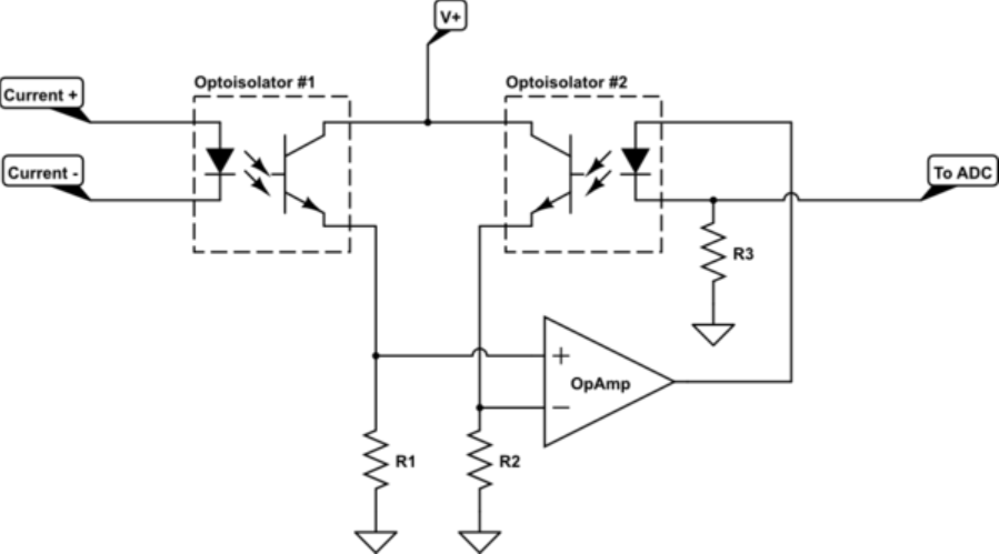
I have built a current loop protection circuit based on the topic Using a microcontroller ADC to measure a 4-20mA sensor

It works good. The next step is I want to protect the input of the circuit from the incorrect hookup. Can I use two Schottky diodes? Would this work correct? I want this circuit to be compatible with 0-10V sensors as well. In that case should I consider the voltage drop by the software when using an ADC? Or maybe there is an other solution?

enter image description here

\$\endgroup\$
2
  • 1
    \$\begingroup\$ Show your circuit. \$\endgroup\$
    – Andy aka
    Commented Jul 12, 2018 at 11:07
  • \$\begingroup\$ i.imgur.com/QXTABNf.png \$\endgroup\$
    – user188731
    Commented Jul 12, 2018 at 11:11

2 Answers 2

2
\$\begingroup\$

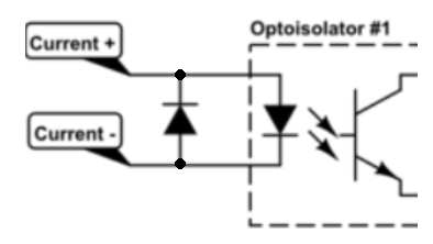
The circuit you linked to is OK of a current loop type sensor. For added protection in the case that the sensor was wired up backwards you just have to add an extra diode like this:

enter image description here

The protection diode would not need to be a Schottky diode.

The same circuit will not really work for a 0->10V sensor output. A resistor load on the sensor in series with the opto coupler LED would require the sensor to source a significant amount of current. Even if the sensor can source a fair amount of current without loss of accuracy there could be loss of accuracy from the series resistance of the wire used to hookup the sensor due to the I2R drop. There is also the forward voltage drop of the LED in the opto coupler to consider as well because this will directly subtract from the sensor output voltage and would not be a linear value.

So you should devise another circuit for your 0->10V sensors.

\$\endgroup\$
0
1
\$\begingroup\$

You are making a home-made galvanic isolator. This is not a very good way of making an isolator. You should use a part that has a single LED and two photodiodes or phototransistors. You have stated no accuracy specification so I won't comment further.

Isolators are non-trivial and you might want to just buy one that has been designed properly.


As far as protection, you should at least have a series resistor on the LED otherwise an incorrect connection from your +24V (typical) loop supply across the LED will burn out the LED instantly. For example if the wires to your two-wire sensor get shorted together (very, very common).

The resistor value will depend on the compliance voltage of your transmitter, the supply voltage and the total resistance of your wiring and receiver(s). The wattage rating should be sufficient to withstand a direct short indefinitely (you could use something like a MOSFET to limit the current if the resistor turns out to be impractical)

\$\endgroup\$

Your Answer

By clicking “Post Your Answer”, you agree to our terms of service and acknowledge you have read our privacy policy.