0
\$\begingroup\$

I got this problem where a inverted pulse of 8µs has to be amplified because the pulse only delivers 10-100µA. The signal will be transmitted over a optocoupler and sent to a mc that interrupts upon receiving the signal. Delay from sensor to mc is acceptable down to 100µs and a longer pulse is acceptable. The ampere meter fuse was blown the ampere was calculated like:

(Vin-Vled)/R=(1.7V-1.2V)/5600=90µA

The reason why Vin was 1.7V was because the current limiter in the pulse generator was pulling the voltage down. With no resistor at all the voltage was roughly 3.3V.

This current has to be amplified to atleast 10mA, but preferably 20mA at 3.3V from the pulse generator to gnd.

Circuit without amplifiers
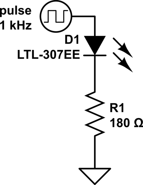
schematic

simulate this circuit – Schematic created using CircuitLab

I tried using a mosfet but the speed was to slow. I also tried the same setup with a npn transistor:
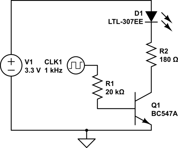
schematic

simulate this circuit

By adding the npn we got the current higher, but only up to 1mA and the voltage was still lower than 3.3V on the pulse generator.

How would you fix this? Should i add another npn, limit the current through the first one to maintain 3.3V? Use a NOT gate? Find another npn with higher current gain? Also i do not want it to be complex since i need to make roughly 20 of these for the pcb.

\$\endgroup\$
2
  • \$\begingroup\$ How sharp do the edges need to be? \$\endgroup\$
    – Hearth
    Commented Jul 29, 2018 at 13:48
  • \$\begingroup\$ Try reducing R1 to 1k. \$\endgroup\$ Commented Jul 29, 2018 at 18:50

2 Answers 2

1
\$\begingroup\$

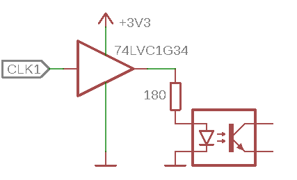
CMOS logic gates have an extremely high input impedance, and most of them have enough drive strength to drive LEDs directly (LVC is rated for 24 mA). In this case, you can use a simple buffer:

If you need multiple buffers, you can have eight with the 74LVC244/74LVC541, or sixteen with the 74LVC16244/74LVC16541.


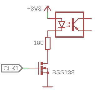
Alternatively, if you want to build it from discrete components, you can switch the LED with a MOSFET that switches on at a low gate voltage and has a small gate capacitance, such as the BSS138:

\$\endgroup\$
0
\$\begingroup\$

schematic

simulate this circuit – Schematic created using CircuitLab

i think there are different ways to do this. but the basic idea should be to have a buffer between the pulse generator and the opto.

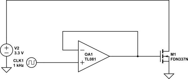
you could use a fast op amp with unity gain. and make that op amp drive a MOSFET(similar to tour circuit above with the npn). The OP- amp has very high input impedance , thus it does not load the pulse generator. In general, MOSFETs switch faster than transistors. The reason you observed the mosfet being slower is because of the limited current that the pulse generator can supply.

alternatively, you use a IC gate driver instead of the op amp such as the MCP1416.

\$\endgroup\$
3
  • \$\begingroup\$ Gate drivers can only output fully on or fully off state. Not suitable for driving MOSFET buffer. \$\endgroup\$
    – Long Pham
    Commented Jul 29, 2018 at 14:00
  • \$\begingroup\$ pulse of the pulse generator would be the input of the gate driver which would drive the MOSFET. so, why wouldn't this work? @LongPham \$\endgroup\$
    – Navaro
    Commented Jul 29, 2018 at 14:29
  • \$\begingroup\$ Oh, sorry, I read only the "amplification" part. If the asker just want to dectect "on" or "off", current comparator is a better option. \$\endgroup\$
    – Long Pham
    Commented Jul 29, 2018 at 15:17

Your Answer

By clicking “Post Your Answer”, you agree to our terms of service and acknowledge you have read our privacy policy.

Not the answer you're looking for? Browse other questions tagged or ask your own question.