3
\$\begingroup\$

I sometimes do electronics projects as a hobby and as far as I know if you want to switch something in a circuit electronically, transistors are the way to go. And I have used them successfully before to control high current loads such as LEDs or DC motors with a micro-controller.

But what I'm trying to do now is to turn a TTL serial connection on and off. As if I was physically disconnecting the TX wire from my micro-controller's RX pin. And I have realized that every tutorial I've ever read about using transistors as switches (this one for example) assume that you are using the transistor to turn a load on or off.

I found a few similar questions on the Internet but they all are drifted away from the subject one way or another and left unanswered. (This and this for example).

I have actually managed to do it myself, with the following circuit: enter image description here
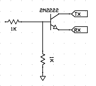
My though process behind this is: A transistor connects the Collector to the Emitter when it is saturated, so when I "turn on" the transistor, TX should get connected to RX. And it actually works!

When nothing is connected to the base my micro doesn't receive anything. When I connect 5V to the base the micro starts receiving serial data. I'm outputting this data to a serial console and it's valid, non-gibberish data.

But having learnt from previous experiences, after achieving this I started searching the Internet to see if this is the proper way to do it. But I couldn't find anything about how to switch a signal/data line on and off. As I mentioned, they are all about switching loads using NPN or PNP transistors to connect to GND or VCC respectively.

What I want is something that acts exactly like a physical switch, that I can put anywhere in the middle of my wire and connect/disconnect it. Which my circuit seems to be achieving.

So am I doing it right or am I just getting lucky?

I have a feeling that I'm just getting lucky.

\$\endgroup\$

4 Answers 4

3
\$\begingroup\$

This is probably not the best way to do this, as the voltage will drop 0.6V across the transistor (assuming its saturated, which it's probably close). For 3.3V TTL the Vih is 2.4V or 2.0V depending on what you have, so odds are you'll still turn on the logic your connecting to. But this isn't the way to do this.

There are better options.

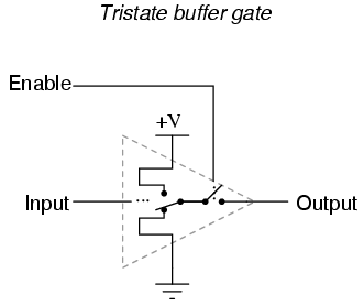
A TLL buffer with an enable line would probably be the best:

enter image description here
Source: https://www.allaboutcircuits.com/textbook/digital/chpt-3/special-output-gates/

There are lots of chips available if you search a distributor (like digikey)

Another way would to use a switch with a low resistance:

enter image description here

The low resistance keeps the voltage from dropping.

\$\endgroup\$
5
  • \$\begingroup\$ In a through-hole package, the available options all seem to be 74x125 or 74x126 ICs. The difference between the two is the polarity of the enable signal -- 125 is active low, 126 is active high. Here's a 125: digikey.com/product-detail/en/texas-instruments/SN74HC125N/… \$\endgroup\$
    – Adam Haun
    Commented Aug 3, 2018 at 20:42
  • \$\begingroup\$ Oh logic gates, of course. Wouldn't an AND gate be enough? Tho I just tried a two-transistor AND gate and it doesn't work. It does work when testing it on an LED but when I AND the TTL signal it doesn't work. \$\endgroup\$
    – Pouria P
    Commented Aug 3, 2018 at 20:42
  • \$\begingroup\$ Yeah, a TLL AND gate should work if thats what you have lying around on your bench. A two transistor AND gate will not work \$\endgroup\$
    – Voltage Spike
    Commented Aug 3, 2018 at 21:00
  • \$\begingroup\$ @laptop2d Why? Because of the voltage drop? \$\endgroup\$
    – Pouria P
    Commented Aug 3, 2018 at 21:54
  • \$\begingroup\$ @VoltageSpike I know this is an old question, but could you comment on why the 2 transistor AND gate wouldn't work? Is it the voltage drop as Pouria P suggests? \$\endgroup\$
    – nall
    Commented Feb 20, 2022 at 0:02
2
\$\begingroup\$

You are just getting lucky. When the transistor is saturated it allows current to flow from collector to emitter, it does not connect these two pins. More importantly, for an NPN transistor to be in saturation the voltage on the base must be about 0.7V higher than the voltage on the emitter, so you generally won't be able to get the emitter voltage up as high as the power supply voltage.

If you want something you can put anywhere in a circuit that behaves like a physical switch then you need an electromechanical relay.

\$\endgroup\$
1
  • \$\begingroup\$ Duh I see. Connecting the emitter to RX means there's no guarantee that it'll ever get saturated. I wonder why it works tho. \$\endgroup\$
    – Pouria P
    Commented Aug 3, 2018 at 21:07
0
\$\begingroup\$

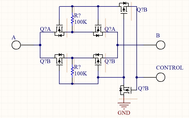
Here's something that can do this generically: enter image description here

It can be simplified for some applications. The practical upshot is that if the CONTROL input is more than one threshold above ground, it will conduct from A to B. No external power is needed other than the control line.

\$\endgroup\$
0
\$\begingroup\$

I finally managed to find a guide about how to switch a signal on/off. In short, you need to use logic gates.

Basically you have three signals. An Input, an Output and a Control signal which decides whether your Output is enabled or not.

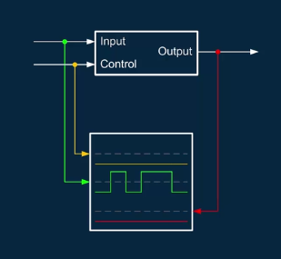
The most common way to achieve this is using an AND gate. In this scenario when your Control signal is low, the output signal will be disabled and forced low:

output signal is disabled when control signal is low

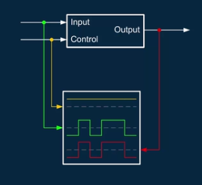
And when your control signal is high the Output signal will be enabled (i.e. the same as your Input signal):

output signal is enabled when control signal is high

Refer to the guide for more information:

https://training.ti.com/tlm-app-enable

\$\endgroup\$

Your Answer

By clicking “Post Your Answer”, you agree to our terms of service and acknowledge you have read our privacy policy.

Not the answer you're looking for? Browse other questions tagged or ask your own question.