1
\$\begingroup\$

I'm designing a board for a DIY synth. One of the circuits consists of an audio amplifier that drives a small 1 W speaker.

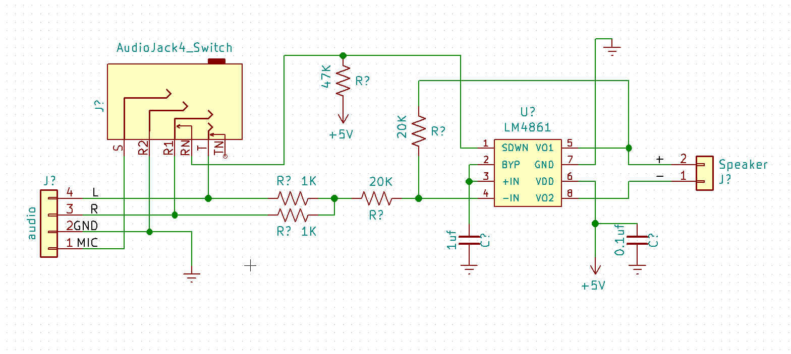
The amplifier takes the signals from a Raspberry hat (a Fe-Pi Audio V2) and I want the amplifier to shut down when a headphone is connected using the switch pins and the shutdown pin on the IC, which is an LM4861

Is the pull-up resistor placed correctly for turning off the amp? Here's the schematics:

Audio Amplifier schematics

\$\endgroup\$
4
  • \$\begingroup\$ What is your question? We don't do design review \$\endgroup\$
    – Voltage Spike
    Commented Aug 3, 2018 at 23:07
  • \$\begingroup\$ my question was: is the pull-up resistor placed correctly for turning off the amp? \$\endgroup\$
    – Cesterino
    Commented Aug 3, 2018 at 23:46
  • \$\begingroup\$ How is this supposed to work? Are you assuming that there's a low-impedance DC path to ground via pin 3 of the "audio" connector? Is that true? \$\endgroup\$
    – Dave Tweed
    Commented Aug 4, 2018 at 1:17
  • \$\begingroup\$ No that's not going to work. but there's not ehough details to in the question to shoose the actual failure mode. \$\endgroup\$ Commented Aug 4, 2018 at 9:10

2 Answers 2

1
\$\begingroup\$

The 47K resistor is correctly placed, but the rest of the circuit has problems.

The LM4861 wants to see audio input centered on half it's supply voltage,

the shutdown pin wants to see less than that voltage else the amplifier shuts down.

So connecting the shutdown pin to R isn't going to work

headphones want to see bipolar audio signals (signals centered on ground, but feeding such signal to the LM4861 will cause clipping)

so with that schematic, whatever comes in from the left the amplifier isn't going to like it - the voltage is either wrong for the shutdown pin or wrong for the -in pin.

best fix is to fit a DC blocking capacitor before the amplifier and bias it up to 1/2VCC and make sure the input to the jack is centered on ground.

If you can, use a socket that has a switch on R2 to control the amplifier

\$\endgroup\$
1
\$\begingroup\$

The problem would be solved simply using a switched sleeve contact but you don't have one. It seems unlikely that you will be using the mic input on the board, however, so you could use that. With a standard 3-pole stereo jack the plug will short out the GND and mic contacts. The only problem now is that you need to invert the logic.

schematic

simulate this circuit – Schematic created using CircuitLab

Figure 1. Shutdown circuit.

With no plug inserted R1 turns on Q1 and pulls SHDN low. Amplification is enabled.

With a 3-pole plug inserted Q1 is turned off and R2 pulls SHDN high.

I've used high-value resistors to minimise current consumption in case it is battery powered. Make your own measurements of the SHDN voltage to confirm reliable operation.

\$\endgroup\$

Your Answer

By clicking “Post Your Answer”, you agree to our terms of service and acknowledge you have read our privacy policy.

Not the answer you're looking for? Browse other questions tagged or ask your own question.