I'm making my first circuit for a line following robot. I already made the prototype, soldered it together, and now I'm at the assembly stage.
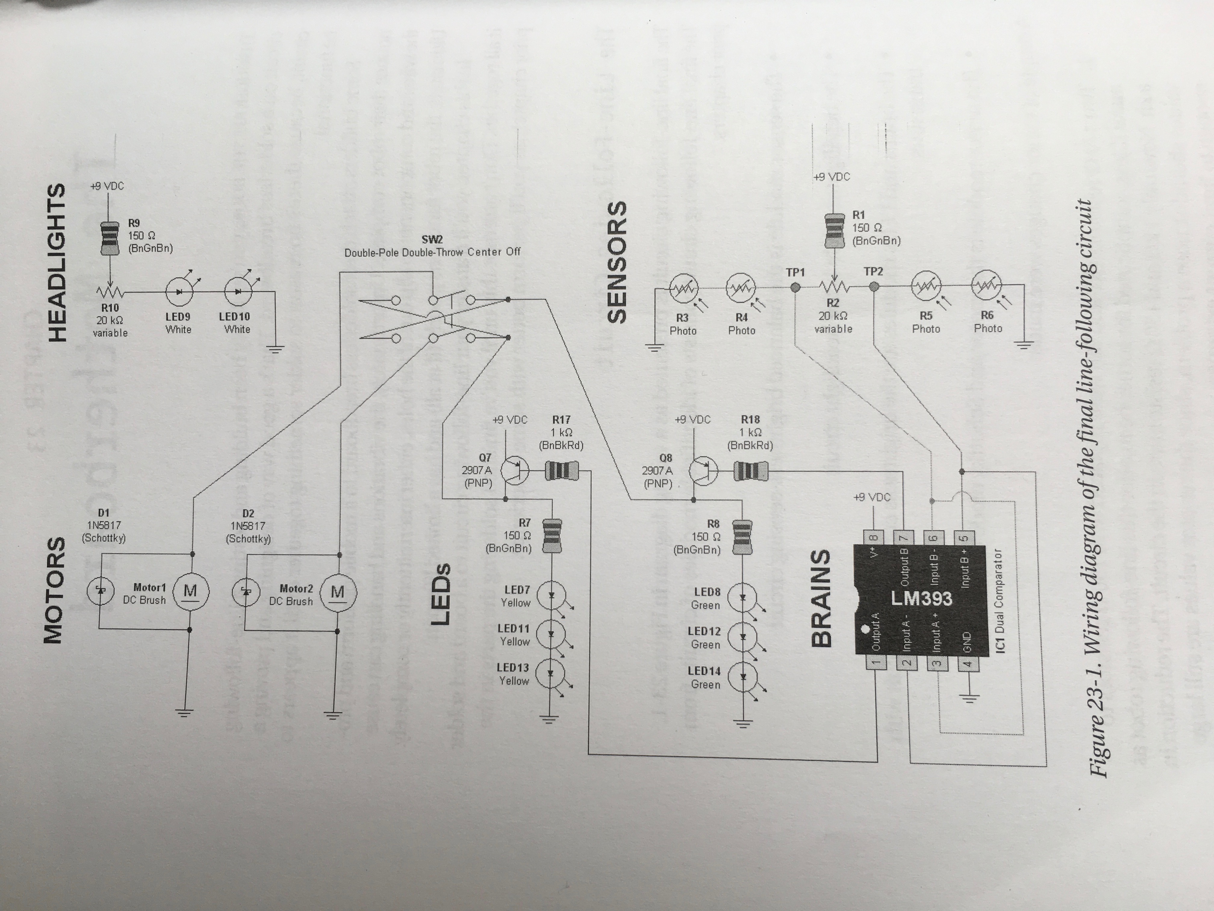
Here is the circuit diagram I'm using:

What should happen is that the LEDs on one side of the circuit (and the corresponding motor) switch on depending on which side of the circuit is receiving more light. The input from the photoresistors is compared by an LM393 comparator chip which switches on the appropriate side of the circuit. The two sides of the comparator chip have their inputs reversed so unless the light level is completely balanced both sets of LEDs should never be on at the same time.
During assembly one of the motors came disconnected so I had to resolder it (my initial soldering was not very good).
Afterwards, my dad connected the battery to test the circuit, but he put it in backwards. As soon as I noticed this I switched the power off.
Prior to the motor breaking, the circuit seemed to be working fine. However, now both sets of LEDs light up and both motors switch on. This is the case even when I completely cover one set of photoresistors. I tested the photoresistors and their resistance does change when I cover them.
I think the problem must be with the IC but I would have assumed that if reversing the battery had broken it then it would just have stopped conducting. Is it possible that it would just give the wrong output instead? I already checked that the IC is correctly wired, and in any case, it was working before the motor disconnected and my dad put the battery in backwards.
Has my IC been fried by the reversed battery or is there another possible problem here?
