0
\$\begingroup\$

I am building a large garden peice in wood, which I hope to illumine from within, powered by a small, (perhaps 90x65, 6v, 0.6w 100mA as space is limited) solar panel. After testing, I noticed that this small power supply is insuficient to even enable a charge controller, let alone charge the USB (1x18650 battery) power stick, I suspect that the current is too low to "wake up" the charge controller?

Whilst considering smaller batteries, or replacing charge controller with a diode, I had a "capacitor" moment, and wondered whether this could be an alternative, if even even better solution?

The ultimate goal is to be able to maintain enough charge during the day to illuminate an LED of any colour (pure white requires a lot more power and pale yellow is more than adequate tho I can use any colours which are more efficient, but I need two of high contrast). I have a photoresistor switch which will also take a little power from the solar panel. Furthermore... I wondered if a combo cap/battery might work well?

My guess is that this is essentially the same circuit used by a solar garden path/accent light... space within the item is not an issue, only the location for the solar collector mounted on the smallest, topmost panel of the assembly, approx 100mm dia.

My reseach so far indicates that a 6v 1F cap can light 12ohm LED for approx 8 hours, but I need far more understanding to know if this calculation is correct, and am very unsure about the resitance of the LED

Any help would be great?

\$\endgroup\$
3
  • \$\begingroup\$ LEDs does not have pure "resistance" like resistors, they have voltage drop: en.wikipedia.org/wiki/Light-emitting_diode#Colors_and_materials \$\endgroup\$ Commented Aug 19, 2018 at 19:29
  • \$\begingroup\$ The simplest is something like this lumenelectronicjewelry.com/2013/02/elemental-lumen you can add a resistor inline and understand that a panel when it is dark out becomes a load and sucks the power out of your cap/battery/storage so a diode to block it helps. do experiments and scale up from there. as commented above though a diode (an led is a diode the d in the name) has a voltage drop not a resistance, so you often us a resistor to offset the difference, if you produce 2.1 volts and the diode is 1.1 the remaining sits across the resistor, put the cap across both and now \$\endgroup\$
    – old_timer
    Commented Aug 20, 2018 at 0:20
  • \$\begingroup\$ gets to see the full output of the panel. It can really start out that simple then you can get as complicated as you want with MPPT circuits and other circuits to detect day vs night and switch the led(s) on and so on and so on. \$\endgroup\$
    – old_timer
    Commented Aug 20, 2018 at 0:22

2 Answers 2

1
\$\begingroup\$

My reseach so far indicates that a 6v 1F cap can light 12ohm LED for approx 8 hours, but I need far more understanding to know if this calculation is correct

6 volts and 1 farad is an energy storage of 18 joules (\$C\cdot V^2/2\$). Spread over 8 hours that's a power of 18/(3600 x 8) watts. So, if you consumed a power of 625 micro watts from your capacitor you would take an energy of 625 micro joules every second and over an hour that would be 2.25 joules and over 8 hours that would be 18 joules.

You also need to consider that only about 75% of that energy is usable because as the capacitor voltage droops below 3 volts your LED driver circuit may falter and switch off the LED.

It's nowhere near enough for even a standard red LED at 1 mA and 2.0 volts.

Any help would be great?

Glad to oblige but I would recommend dismantling one of those garden lights to see what they use then scale up your PV panel and battery/supercap accordingly to match your needs.

\$\endgroup\$
0
\$\begingroup\$

You need to harvest and store the solar energy.

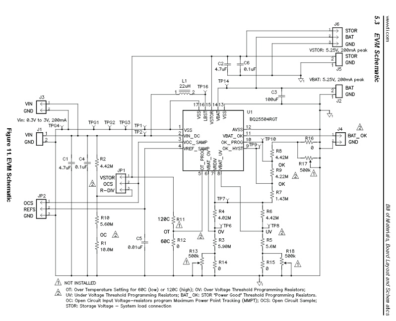
This $5. 3 mm x 3 mm, TI BQ25504 Energy Harvester was made especially for a solar battery charging project. It takes an input of 80 mV to 3V at 330 nA up to 200 mA to charge a super cap or Li-ion battery.

This single chip does it all. Requires 4 caps, 10 resistors, and a 22µH inductor.


This is a schematic of a 1.8" x 1.8" (45 mm x 45 mm) evaluation PCB.

enter image description here

\$\endgroup\$
4
  • \$\begingroup\$ It's a good chip but it's maximum input voltage is 5.5 volts and the solar panel is 6 volts. Maybe a different panel would be an option? \$\endgroup\$
    – Andy aka
    Commented Aug 19, 2018 at 18:49
  • \$\begingroup\$ @Andyaka absolutely. TI says "single or dual-cell solar panels" \$\endgroup\$ Commented Aug 19, 2018 at 18:57
  • \$\begingroup\$ Wow, this looks great... a breif examination brings the first question... There seems to be a low voltage cut off (UV resistors)... can this feature be used insead of a photoresistor switch to illuminate the LED? Perhaps I am asking too much \$\endgroup\$
    – Axe
    Commented Aug 20, 2018 at 1:08
  • \$\begingroup\$ The Under Voltage (UV) is specific to the battery being charged. Have you seen the Eval board? ti.com/lit/ug/sluu654a/sluu654a.pdf You should also read: batteryuniversity.com/learn/article/… The on-off circuit would be has nothing to do with UV and would be included in the "SYSTEM LOAD" block in the schematic on page 1 of the datasheet. \$\endgroup\$ Commented Aug 20, 2018 at 1:57

Your Answer

By clicking “Post Your Answer”, you agree to our terms of service and acknowledge you have read our privacy policy.

Not the answer you're looking for? Browse other questions tagged or ask your own question.