2
\$\begingroup\$

Ok, I have a differentiator with an OpAmp, a resistor and a capacitor. I've calculated the response function, and I've written it in the picture.
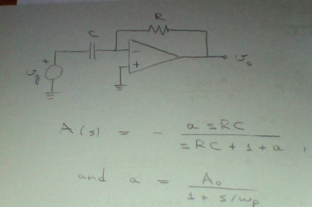
Differentiator

Now, the OpAmp has a single-pole response function, that is also on the paper, and I need to see how will the final Amplitude and Phase characteristics look like (Bode Plots of course). When we substitute the two expressions, we get:

\$ \displaystyle A(s)=\frac{A_0s}{s^2+s(\omega_p + \frac{1}{RC})+\frac{\omega_p(A_0+1)}{RC}} \$

Now we have a quadratic function, and in the general case, this will look strange on a bode plot if there aren't real solutions to the equation.

I mean, looking at the theory, and what I would suppose is that this should be a nice differentiator, with an amplitude bode plot looking normally, just with a pole on higher frequencies, sth like:
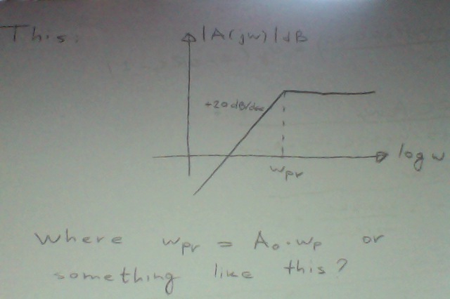
Plot

But I have no idea if this is actually right, and if yes, why. Any help? :)

\$\endgroup\$

1 Answer 1

1
\$\begingroup\$

I see three main errors :-

First, your transfer function is missing a term in \$\omega_P\$ in the numerator.

\$A(s) = \dfrac{-A_0\omega_Ps}{s^2+s(\omega_P+\frac{1}{RC})+\frac{\omega_P(A_0+1)}{RC}}\$

Second, the natural frequency should be :-

\$\omega_{PV} = \sqrt\frac{\omega_P(A_0+1)}{RC}\$

Third, your bode plot should fall at 20dB/decade above the natural frequency.

In practice, real differentiators made this way tend to have high Q (low damping) giving a high peak in the transfer function at the natural frequency causing severe ringing. This can be reduced by putting a small resistor in series with the capacitor.

\$\endgroup\$
8
  • \$\begingroup\$ Yeah, an NF filter gets rid of that stuff right? Coming back to your second point though, how have you gotten that expression for \$\displaystyle\omega_{PV}]\$? I suppose that maybe you can say something like: \$\displaystyle A(s)\approx-\frac{A_0\omega_Ps}{(s+\omega_{PV})^2}\$, and then you get your result? \$\endgroup\$
    – Vidak
    Commented Sep 18, 2012 at 15:01
  • \$\begingroup\$ The general form of a second-order characteristic equation (denominator) is \$s^2+2\zeta\omega_ns+\omega_n^2\$ where \$\omega_n\$ is the natural frequency and \$\zeta\$ is the damping factor. So the natural frequency is the square root of the last term. This comes from the fact that at the natural frequency, \$s^2+\omega_n^2 = 0\$. \$\endgroup\$
    – MikeJ-UK
    Commented Sep 18, 2012 at 15:11
  • \$\begingroup\$ I don't get it, what if we have like \$\omega_{p1}=3 \frac{rad}{s}\$ and \$\omega_{p2}=5\frac{rad}{s}\$, so the denominator is:\$\displaystyle (s+5)(s+3)=s^2+8s+15\$, and then the natural frequency would be \$\omega_{PV}=\sqrt{15}\approx 4\$, and the plot would have a double pole in \$\omega=4\$, instead of two poles in \$5\$ and \$3\$, respectively? Addressing your previous point, would the characteristic look something like this? \$\endgroup\$
    – Vidak
    Commented Sep 18, 2012 at 15:36
  • \$\begingroup\$ In the case of real roots, the idea of natural frequency doesn't really apply (although it is still the frequency of maximum gain). So yes, the natural frequency in your example is 3.87 rad/sec even though the poles are different. Your new bode plot is correct but assumes two identical roots (for example wp1=wp2=4) although if you put some real numbers in, you will usually see a peak where the two lines meet due to the poles becoming complex (low damping). \$\endgroup\$
    – MikeJ-UK
    Commented Sep 18, 2012 at 15:54
  • \$\begingroup\$ I'm pretty rusty but the graph he drew is magnitude only. Wouldn't complex poles primarily affect the phase of the system, not the magnitude? \$\endgroup\$
    – AngryEE
    Commented Sep 18, 2012 at 15:58

Your Answer

By clicking “Post Your Answer”, you agree to our terms of service and acknowledge you have read our privacy policy.

Not the answer you're looking for? Browse other questions tagged or ask your own question.