14
\$\begingroup\$

My project needs to drive a medium power ultrasonic piezoelectric transducer from a sine wave (/ sawtooth) sweep generator that sweeps +/- 2% of the transducer resonant frequency.

The question: What are my simplest options for driving these transducers from a DDS generated shaped signal, with reasonably low distortion (5-10%)?

  1. Use a power amplifier IC off a higher voltage rail, with lots of heat sinking, to directly drive the transducer
  2. Use a power amplifier IC, then (?) a transistor current amplification stage, then an appropriate (need help identifying) step-up transformer to drive the transducer
  3. Use some sort of (need help identifying) class D high power amplifier IC that would not need much heat sinking (Edit: Not a solution, see Note 7).
  4. Some other option entirely
  5. Edit: From suggestion below Identify an off the shelf OEM amplifier module that meets the parameters and constraints.

UPDATE: [15-Oct-2012] Option 5 above seems best answer, if a suitable OEM module or two could be pointed out - None found in my research so far. Hence leaving question open.


The sweep waveform generation is through a DDS IC, AD9850, Datasheet here: AD9850 CMOS 125 MHz Complete DDS Synthesizer

One of the transducers available to me: 5938D-25LBPZT-4 (Ultrasonic Langevin Transducers)

  • Resonant frequency: 25 KHz
  • Resonant impedance: 10-20 Ohms
  • Capacitance: 5400 pf +/-10%
  • Input power: 60W
  • Datasheet: I wish I could find one!

The transducer would change case to case, from 20KHz to 135KHz, each in the 50-250 watt range, similar in design to the one above.

The driver designs I have seen for these transducers typically use switching i.e. square waves to drive them, MOSFET driven, with Vpp 100v in some cases! (Do these devices even need that kind of voltage? Edit: Evidently so)

Some drivers use tuned filters to shape the waveform to a sine or approximation thereof.

This does not work for my purposes, unfortunately - The project is a single device that would first detect the resonant frequencies of an attached transducer across the full range 20-135KHz, then sweep around each resonant frequency with first a sine wave, (Edit: Removing this requirement as unfeasible: then a sawtooth signal,) at a specified power output, usually around half the rated power of the transducer.

So what I am looking for is the wisdom of this community in suggesting a suitable prototype-friendly approach to getting those DDS waveforms over to the transducer. Thank you all!


Added some notes based on comments and responses received:

  1. Waveform accuracy is not super-critical, 5% distortion is very acceptable. Thermal issues and power wastage through dissipation in the amplifier stage are bigger concerns. Cost is a key concern, at least until past the prototype stage.
  2. It has been suggested that prebuilt OEM amplifier modules that suit the requirements might be my best bet. While that does appeal, I am still hoping for alternatives in addition to, and examination of, the options I have proposed in my question, hence not marking the answer accepted, yet.
  3. Not found any OEM module online yet which covers a 20KHz to 135KHz frequency range, even for 50 watt output. The one suggested in a response is designed for 3.5KHz, and its switching frequency is 100KHz. (Dropped this requirement: Also, wouldn't I require bandwidth much higher than that, to handle a sawtooth wave with even cursory accuracy? I might have to skip the sawtooth requirement, and constrain my question to sine waves, if the sawtooth or other arbitrary waveform delivery is seen by respondents as unattainable at reasonable cost.)
  4. New Suggested approach is a Class B with feedback. Caveat mentioned is high dissipation at this amplifier stage. So two adjuncts to my question:
  5. Is there a monolithic Class B amplifier IC that might cover the desired frequency range (20KHz to 135KHz, giving up on the sawtooth wave) and power requirements (50 watts max)?
  6. What is the range of heat dissipation expected at such a class B stage, as a percentage of expected power delivery to transducer?
  7. New About Class D amplifiers, monolithic or OEM: They would need to use switching frequencies of the order of 800KHz or higher, to support a 100-135KHz sine wave with reasonable THD. For a 5% distortion requirement, the switching frequency must be even higher. Such high switching frequency Class D power amplifiers do not seem to exist.
\$\endgroup\$
6
  • \$\begingroup\$ Good question, I'm waiting for somebody's answer to this question. +1. \$\endgroup\$ Commented Oct 10, 2012 at 8:06
  • \$\begingroup\$ There is tradeoff between the simplicity of the solution and the accuracy of the transmitted waveform. What is your application? Is it a device metrology problem or an ultrasound problem you are trying to solve? \$\endgroup\$
    – ARF
    Commented Oct 10, 2012 at 10:31
  • \$\begingroup\$ The application is a lab-condition diagnostic device: Purity of waveform is important but not critical - hence the 5-10% distortion being acceptable. \$\endgroup\$ Commented Oct 10, 2012 at 11:19
  • \$\begingroup\$ Not sure if these will work for you, but much lower cost; piezodrive.com/modules.html#pdu100b \$\endgroup\$
    – user71967
    Commented Apr 10, 2015 at 16:48
  • \$\begingroup\$ going out on a limb here, has any one considered vacuum tube technology, possibly a home brew version could be attainable? \$\endgroup\$
    – user114969
    Commented Jun 25, 2016 at 6:29

5 Answers 5

5
\$\begingroup\$

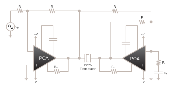
Try these linear amplifiers made by Apex. They are designed specifically for ultrasound aplications.

enter image description here

\$\endgroup\$
2
  • \$\begingroup\$ Datasheet links please? \$\endgroup\$ Commented Aug 29, 2013 at 4:09
  • 3
    \$\begingroup\$ No part number and dead link... \$\endgroup\$
    – Drew
    Commented Sep 6, 2019 at 5:45
3
\$\begingroup\$

In many ultrasonics applications you really will need to work with potential differences in excess of 100V to deliver sufficient acoustic power to the medium. This is due to the fairly low impedance the transducers present electrically. Predicting how much voltage you need to achieve a set acoustic pressure however is next to impossible as the transfer functions are non-trivial.

Many ultrasound applications are not terribly concerned with the excitation waveform. This is the reason why many power amplifier stages are very simple push-pull configurations giving a square wave output. Their advantage is two-fold:

  1. they can be driven easily from low-voltage signal generation circuits, and
  2. they dissipate very little power in the switching elements which is a common design constraint. (Due to the fact that ultrasound transducers are fairly narrow-band, the energy dissipation is shifted to the cable and transducer. Often cooling the transducer is much easier.)

In situations where signal waveform is important, the power amplifier stages I encountered in the past were generally class B push-pull configurations with negative feedback to avoid crossover distortion fed from high-voltage rails. It sounds to me that this would be the way to go in your situation. Note: there will be non-negligible power dissipated in your switching elements.

\$\endgroup\$
1
  • \$\begingroup\$ Thanks... Would you have any suggestions on OEM class B amp modules that cover the 20KHz to 135KHz range? I understand that there will be a fair bit of heat dissipation at the amplifier stage - I assume that's the switching stage you refer to. Is it a safe assumption that this dissipation will be at worst 15% to 30% of the desired output power? Or do I have my math all wrong on this? \$\endgroup\$ Commented Oct 11, 2012 at 12:18
2
\$\begingroup\$

I think the Piezo Systems EPA-104-115 fits all your criteria except for the low-cost criteria. It costs $2,639.

The AA Lab Systems A-301HS may also fit and is probably as cheap as you'll find. I saw one on ebay for $975.

Searching for piezo driver or piezo linear amplifier didn't turn up anything more affordable in my search, but feel free to double check yourself.

You might also want to read this paper written by a lab that built a less expensive driver for their piezo actuators. Unfortunately their driver is in the 1kHz range but they end by suggesting some methods that might get the kHz up. On the other hand, they say they aren't sure where to get parts that could handle higher frequencies, but it may be a helpful read to understand what makes higher frequencies difficult and could lead toward a solution with some perseverance.

\$\endgroup\$
1
\$\begingroup\$

First of all, yes, you will need voltages on the order of 100V peak (70.7V RMS) to drive 250W into 20Ω.

You can purchase OEM power amplifier modules that cover the power and frequency range you're interested in; this is probably your best bet in terms of getting the prototype operating quickly with low design risk. It may even be the way to go for production, as well. Be sure to select a unit that can deal with the capacitive load.

Here is one example. Interestingly, I find that audio power amplifier modules these days are almost exclusively class-D, with the bandwith limited to 10s of kHz. When I last looked at these some years ago, they were class-AB and had bandwidths of 100s of kHz. Be sure to include "piezo" or "ultrasonic" in your search terms.

\$\endgroup\$
2
  • \$\begingroup\$ Thanks... If you could point me at some OEM power amplifiers that might serve the purpose, or even a site I could look at, that would work well at least for the prototype stage. For this stage, even a 50 to 100 watt power output would work well. \$\endgroup\$ Commented Oct 10, 2012 at 11:50
  • \$\begingroup\$ The example device linked has a stated bandwidth of 3.5KHz, which unfortunately is not close to the requirements of my question. PI does not have any offerings for my frequency range, but they were nice enough to explain that it would be unlikely to find a Class D that is usable beyond about 30KHz sine, that too with heavy distortion, since they typically use 100KHz switching frequency, and Nyquist comes into play. Editing this finding into my question. \$\endgroup\$ Commented Oct 11, 2012 at 16:51
1
\$\begingroup\$

I would observe that a standard piezo or piezo composite transducer has a bandwidth of maybe 20% or so (Possibly an octave with a fairly hardcore matching network for tuning), there is a reason everyone does square wave drive, and it is that the transducers just do not have enough bandwidth to reproduce anything other then a sine wave, it literally does not matter what the drive waveform is the transducer will bandpass it into a sine wave....

Further even within that bandwidth the group delay varies widely,to the point that even putting a reasonably square multi cycle pulse into the water is difficult enough that Paul Doust used to use it as a party trick demo (As in a squareish burst of sine waves).

I would suggest that whatever you do, a modest (few ohms or so) power resistor in series with the amplifier output would be a good idea to help phase margin.

There are audio amps what will do what you want, but cheap? Not so much, and as I say a H bridge is all you really need because of the transducer limitations (The exception is multiple tones within the available bandwidth where intermod can be an issue).

Class D with GaN might be an option but nobody really has product yet.

Regards, Dan.

\$\endgroup\$

Not the answer you're looking for? Browse other questions tagged or ask your own question.