6
\$\begingroup\$

I have done a search on here but didn't find the answer (maybe "woods for the trees") but here goes...

A brief 'background' -- In my house, there's a switch by my front door that turns on/off the outside light above the door. The wiring is obviously cemented in place and has been for 15+ years that I know of... Where the light is, there's a round junction box of sorts, wiring is buried in solid walls etc so, for now at least, re-wiring is NOT an option. The oddity is that, there is 2 feeds at this point - and they are the opposite of each other. 1 is connected to the exterior light, the other is connected to nothing. When the Light is ON, the other feed is off, when the light is OFF, the other feed is ON. I've no idea why!

Anyways, this is the only feasible external power supply point to use for a CCTV camera being fitted (2 actually, Using MotionEyeOS - a Raspberry Pi OS for using a Pi as a CCTV system).

What I had done as a temporary measure, was I wired in 2 sockets, and simply plugged in a 5v USB plug in each. They then joined via a USB Y cable, and connected to a PowerBank device that is capable of charging whilst simultaneously powering 2 connected devices to a max of 3.1A (1 USB Port is 2.1A, the 2nd is 1A) - and then the Raspberry (x2) were connected to the powerbank. This worked nicely for some time, but of course, due to the power consumption of the 2x Raspberry's, it's power eventually depletes quicker than it can charge.

This brings me to my question - how can I wire these sockets (is there something I can buy?, or do I need to make a circuit?) so that the power to the Raspberry Pi's is not cut momentarily when turning the light on and off? - In other words, How can I keep the 2x Raspberry Pi's powered when the switch is turned on or off? (and the power switches from one feed to another)

Note: Total power usage would be 5v x 2, and 2.5A max x 2 (So 5v, 5A max)

I realise the power loss would be something like a nano second, but I imagine it still has potential to lead to untold issues!?

\$\endgroup\$
7
  • \$\begingroup\$ Sounds like your outside light switch is a 2-way, with one feed wired to each. This is the way you would connect a second switch to allow the light to be controlled from two different places. \$\endgroup\$
    – Finbarr
    Commented Apr 14, 2019 at 23:07
  • 1
    \$\begingroup\$ And an interruption of one nano second won't cause you any problems. But connecting power supply outputs together with just a cable might. \$\endgroup\$
    – Finbarr
    Commented Apr 14, 2019 at 23:12
  • \$\begingroup\$ @Finbarr - Thanks :) I figured it was a 2 way switch, I'm just not sure why they (whoever it was) did it. I haven't joined the 2 mains supplies together, I wired a single socket to each, then plugged in a 5v USB power supply to each, and used the USB Y to join them. In my head I though that was "safer" than just connecting the supplies directly together (the 5v plugs are not cheap crap ones, they're properly regulated with reverse protection etc etc). Also, the Raspberry's use SD cards which are volatile and susceptible to corruption especially in voltage issues \$\endgroup\$
    – IAmOrion
    Commented Apr 14, 2019 at 23:23
  • 1
    \$\begingroup\$ They may have done it to allow a second switch to be added later. Or perhaps they put one in and it was later taken out. \$\endgroup\$
    – Finbarr
    Commented Apr 14, 2019 at 23:35
  • 1
    \$\begingroup\$ Get it rewired so the unused cable is always powered? \$\endgroup\$ Commented Apr 15, 2019 at 0:19

2 Answers 2

1
\$\begingroup\$

Looks to me like the original installation was meant to be one light controlled by two switches. That’s where one switch switches the power to a 2nd parallel line, and the second switch switches line in the same way. If both switches are connected to the same line, the light is on. So either switch can turn the light on/off. Used for a room with one light controlled at two doors. That’s exactly what Finbar said in his reply. Rudy’s second diagram doesn’t seem to fit. I’m puzzled that you said one feed was connected to “nothing”, and then said the power was switched over to that line. It’s obviously connected to something.

Another possibility is that the installation only required a 1-way switch, but the installer used a 2-way switch instead. And if the power was coming from the light, and not going to it, both switch poles would see power when the switch was thrown their way. That explains why the power changed to each pole when the switch was thrown. Repeat your testing with the bulb removed. That will remove power from the switch. If you want continuous power, connect to the live line where the bulb is.

\$\endgroup\$
1
  • \$\begingroup\$ It could very well be connected to nothing other than the switch, however; i.e., no downstream load. \$\endgroup\$
    – Hearth
    Commented Jun 23, 2021 at 14:45
0
\$\begingroup\$

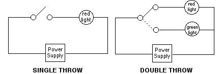
It sounds like someone installed a "double throw" switch. (aka three way switch)

two pole switch

Consider the circuit on the right. The red light is the one connected to your exterior light. And the other wire connected to the green light (in the image) is the extra circuit that goes nowhere.

What I would do is disconnect the wire on the switch that goes to the green light (the one that goes nowhere) and connect it to the power feeding the switch. (the left side of the switch) You then would have continuous power on that line regardless of the switch position. This would be a lot simpler than trying to cobble something together as you described above. While it is an option I would prefer the simpler approach.

\$\endgroup\$
5
  • \$\begingroup\$ That's a two way switch, not three way. \$\endgroup\$
    – Finbarr
    Commented Apr 14, 2019 at 23:34
  • 3
    \$\begingroup\$ I know what it is, but that's what it also is referred to when it comes to electrical wiring for two switches controlling one lamp/load in North America. I know it is crazy but that is how it is referred to. en.wikipedia.org/wiki/… \$\endgroup\$
    – Rudy
    Commented Apr 14, 2019 at 23:58
  • \$\begingroup\$ @Rudy thanks for the info - so to clarify, you're suggesting removing the light switch itself, and change the connections to suit, so that the "other" supply is always live, whilst the light still remains switched? \$\endgroup\$
    – IAmOrion
    Commented Apr 15, 2019 at 1:37
  • \$\begingroup\$ Yes. There seems to be no purpose for that switched line. And since it is not being used then why not use it to bring out continuous power that you require. It is a line that is already there. Just confirm that the what I believe is there really is. Connections to the switch, more than a single pole switch. \$\endgroup\$
    – Rudy
    Commented Apr 15, 2019 at 1:38
  • \$\begingroup\$ @Rudy The US electricians' terminology is not crazy at all if you consider that the "ways" are not counting switching positions, but wire terminals. Consider a "4-way" switch. \$\endgroup\$
    – Theodore
    Commented Jun 23, 2021 at 15:35

Your Answer

By clicking “Post Your Answer”, you agree to our terms of service and acknowledge you have read our privacy policy.

Not the answer you're looking for? Browse other questions tagged or ask your own question.