Thanks in advance for your time.
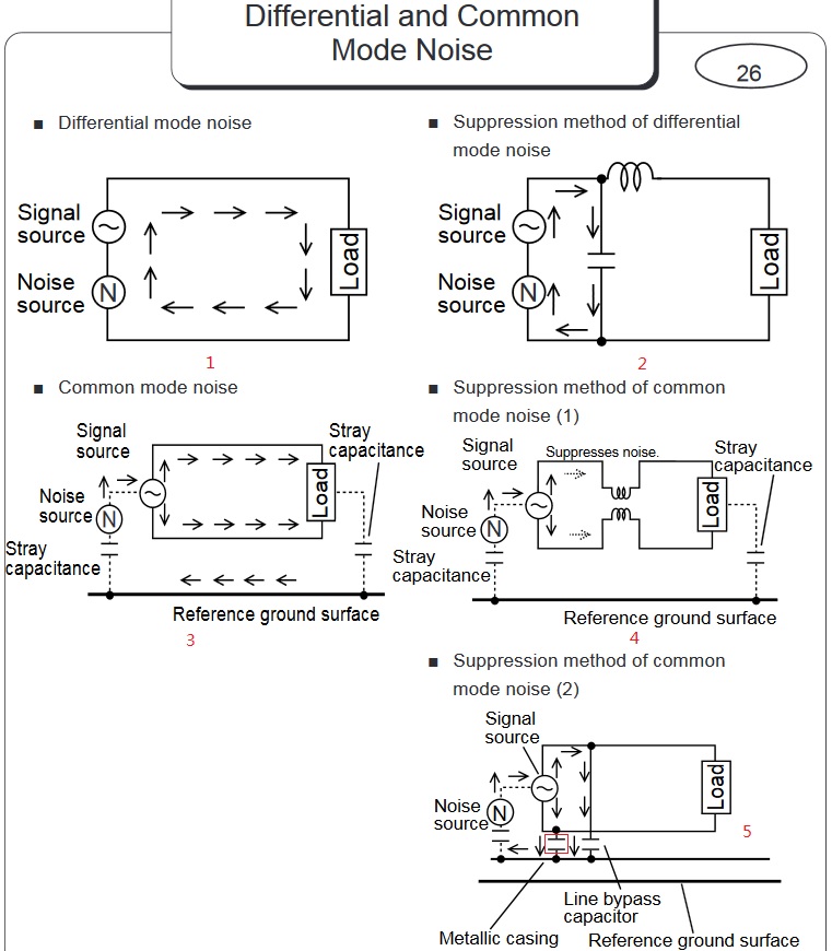
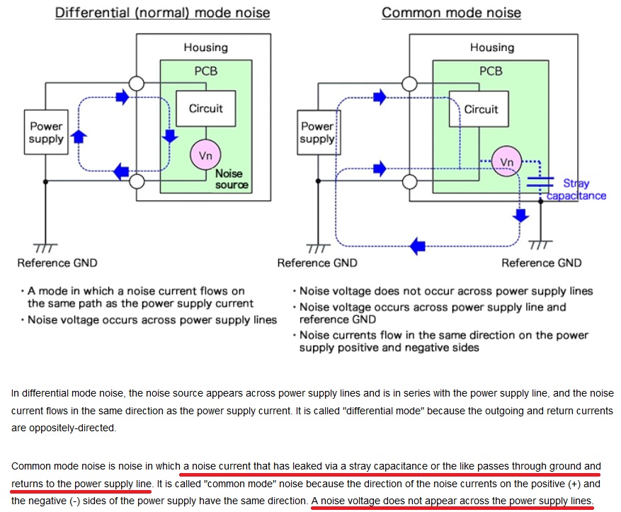
I am reading several articles about differential mode noise and common mode noise. Among which I found the below 2 pretty instructive:
https://www.murata.com/~/media/webrenewal/products/emc/emifil/knowhow/26to30.ashx https://micro.rohm.com/en/techweb/knowledge/emc/s-emc/01-s-emc/6899
Let me first talk about my understanding as a start point.
Differential mode noise is some noise generated with the propagation of power line, such as noise generated from some on-board chips' operation like source/sink power to GND. This will produce ripple on power line, which is noise. In this case, placing capacitor between power and GND line solves the problem, it conduct the noise current to GND and flow back to power source. This is illustrated in Figure marked 1 and 2.
Common mode noise is pretty confusing. It is generated through the coupling between your on board signal trace or plane and the Earth GND. The start point is, there is coupling between your on board trace or plane and the surrounding mechanical box which is connected to Earth Ground, so this coupling will generate some current through it. Then this coupling current will flow back to your power supply's Earth GND, which its surrounding mechanical box is connected to, then through its stray capacitance, the noise will flow to both the power and GND lines that the power supply feed to your board. This is the signal flow of common mode noise.
Is my understanding correct?
My questions are:
In the first article, Suppression method of common mode noise (2), it says adding cap between signal GND and earth GND solve common mode noise, why? I understand method (1), using common mode choke, but why method (2) also works? Just because common mode noise is referenced to Earth GND, so placing cap between where common mode noise flow through and Earth GND, can filter it out?
Why doesn't differential mode noise's current go with the common mode noise's path?

